


Load factors: airplane operating limits.
The preceding sections from the subpages of the Airplane page only briefly considered some of the practical points of the principles of flight. To become a pilot, a detailed technical course in the science of aerodynamics is not necessary. However, with responsibilities for the safety of passengers, the competent pilot must have a well-founded concept of the forces which act on the airplane, and the advantageous use of these forces, as well as the operating limitations of the particular airplane. Any force applied to an airplane to deflect its flight from a straight line produces a stress on its structure; the amount of this force is termed “load factor.” A load factor is the ratio of the total airload acting on the airplane to the gross weight of the airplane. For example, a load factor of 3 means that the total load on an airplane’s structure is three times its gross weight. Load factors are usually expressed in terms of “G”—that is, a load factor of 3 may be spoken of as 3 G’s, or a load factor of 4 as 4 G’s. It is interesting to note that in subjecting an airplane to 3 G’s in a pullup from a dive, one will be pressed down into the seat with a force equal to three times the person’s weight. Thus, an idea of the magnitude of the load factor obtained in any maneuver can be determined by considering the degree to which one is pressed down into the seat. Since the operating speed of modern airplanes has increased significantly, this effect has become so pronounced that it is a primary consideration in the design of the structure for all airplanes. With the structural design of airplanes planned to withstand only a certain amount of overload, a knowledge of load factors has become essential for all pilots. Load factors are important to the pilot for two distinct reasons: 1. Because of the obviously dangerous overload that is possible for a pilot to impose on the airplane structures; and 2. Because an increased load factor increases the stalling speed and makes stalls possible at seemingly safe flight speeds. Load factors in airplane design The answer to the question “how strong should an airplane be” is determined largely by the use to which the airplane will be subjected. This is a difficult problem, because the maximum possible loads are much too high for use in efficient design. It is true that any pilot can make a very hard landing or an extremely sharp pullup from a dive, which would result in abnormal loads. However, such extremely abnormal loads must be dismissed somewhat if airplanes are built that will take off quickly, land slowly, and carry a worthwhile payload. The problem of load factors in airplane design then reduces to that of determining the highest load factors that can be expected in normal operation under various operational situations. These load factors are called “limit load factors.” For reasons of safety, it is required that the airplane be designed to withstand these load factors without any structural damage. Although the Code of Federal Regulations requires that the airplane structure be capable of supporting one and one-half times these limit load factors without failure, it is accepted that parts of the airplane may bend or twist under these loads and that some structural damage may occur. This 1.5 value is called the “factor of safety” and provides, to some extent, for loads higher than those expected under normal and reasonable operation. However, this strength reserve is not something which pilots should willfully abuse; rather it is there for their protection when they encounter unexpected conditions. The above considerations apply to all loading conditions, whether they be due to gusts, maneuvers, or landings. The gust load factor requirements now in effect are substantially the same as those that have been in existence for years. Hundreds of thousands of operational hours have proven them adequate for safety. Since the pilot has little control over gust load factors (except to reduce the airplane’s speed when rough air is encountered), the gust loading requirements are substantially the same for most general aviation type airplanes regardless of their operational use. Generally, the gust load factors control the design of airplanes which are intended for strictly nonacrobatic usage. An entirely different situation exists in airplane design with maneuvering load factors. It is necessary to discuss this matter separately with respect to: (1) Airplanes which are designed in accordance with the Category System (i.e., Normal, Utility, Acrobatic); and (2) Airplanes of older design which were built to requirements which did not provide for operational categories. Airplanes designed under the Category System are readily identified by a placard in the cockpit, which states the operational category (or categories) in which the airplane is certificated. The maximum safe load factors (limit load factors) specified for airplanes in the various categories are as follows: CATEGORY LIMIT LOAD Normal* 3.8 to –1.52 Utility (mild acrobatics, including spins) 4.4 to –1.76 Acrobatic 6.0 to –3.0 * For airplanes with gross weight of more than 4,000 pounds, the limit load factor is reduced. To the limit loads given above, a safety factor of 50 percent is added. There is an upward graduation in load factor with the increasing severity of maneuvers. The Category System provides for obtaining the maximum utility of an airplane. If normal operation alone is intended, the required load factor (and consequently the weight of the airplane) is less than if the airplane is to be employed in training or acrobatic maneuvers as they result in higher maneuvering loads. Airplanes that do not have the category placard are designs that were constructed under earlier engineering requirements in which no operational restrictions were specifically given to the pilots. For airplanes of this type (up to weights of about 4,000 pounds) the required strength is comparable to present-day utility category airplanes, and the same types of operation are permissible. For airplanes of this type over 4,000 pounds, the load factors decrease with weight so that these airplanes should be regarded as being comparable to the normal category airplanes designed under the Category System, and they should be operated accordingly. Load factors in steep turns In a constant altitude, coordinated turn in any airplane, the load factor is the result of two forces: centrifugal force and gravity.
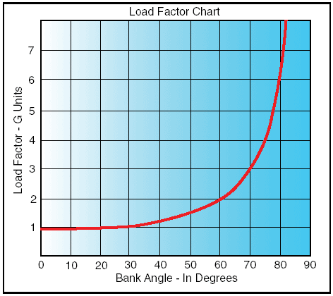
Figure 1: Two forces cause load factor during turns. For any given bank angle, the rate of turn varies with the airspeed; the higher the speed, the slower the rate of turn. This compensates for added centrifugal force, allowing the load factor to remain the same. Figure 2 reveals an important fact about turns— that the load factor increases at a terrific rate after a bank has reached 45° or 50°. The load factor for any airplane in a 60° bank is 2 G’s. The load factor in an 80° bank is 5.76 G’s. The wing must produce lift equal to these load factors if altitude is to be maintained.
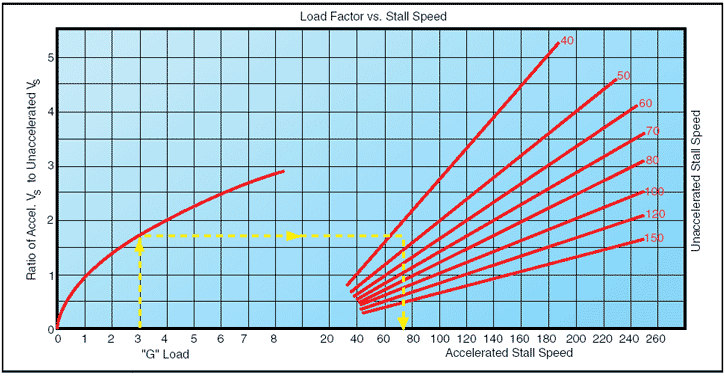
Figure 2: Angle of bank changes load factor. It should be noted how rapidly the line denoting load factor rises as it approaches the 90° bank line, which it reaches only at infinity. The 90° banked, constant altitude turn mathematically is not possible. True, an airplane may be banked to 90° but not in a coordinated turn; an airplane which can be held in a 90° banked slipping turn is capable of straight knifeedged flight. At slightly more than 80°, the load factor exceeds the limit of 6 G’s, the limit load factor of an acrobatic airplane. For a coordinated, constant altitude turn, the approximate maximum bank for the average general aviation airplane is 60°. This bank and its resultant necessary power setting reach the limit of this type of airplane. An additional 10° bank will increase the load factor by approximately 1 G, bringing it close to the yield point established for these airplanes. Load factors and stalling speeds Any airplane, within the limits of its structure, may be stalled at any airspeed. When a sufficiently high angle of attack is imposed, the smooth flow of air over an airfoil breaks up and separates, producing an abrupt change of flight characteristics and a sudden loss of lift, which results in a stall. A study of this effect has revealed that the airplane’s stalling speed increases in proportion to the square root of the load factor. This means that an airplane with a normal unaccelerated stalling speed of 50 knots can be stalled at 100 knots by inducing a load factor of 4 G’s. If it were possible for this airplane to withstand a load factor of 9, it could be stalled at a speed of 150 knots. Therefore, a competent pilot should be aware of the following: • The danger of inadvertently stalling the airplane by increasing the load factor, as in a steep turn or spiral; and • That in intentionally stalling an airplane above its design maneuvering speed, a tremendous load factor is imposed. Reference to the charts in figures 2 and 3 will show that by banking the airplane to just beyond 72° in a steep turn produces a load factor of 3, and the stalling speed is increased significantly. If this turn is made in an airplane with a normal unaccelerated stalling speed of 45 knots, the airspeed must be kept above 75 knots to prevent inducing a stall. A similar effect is experienced in a quick pullup, or any maneuver producing load factors above 1 G. This has been the cause of accidents resulting from a sudden, unexpected loss of control, particularly in a steep turn or abrupt application of the back elevator control near the ground.
Figure 3: Load factor changes stall speed. Since the load factor squares as the stalling speed doubles, it may be realized that tremendous loads may be imposed on structures by stalling an airplane at relatively high airspeeds. The maximum speed at which an airplane may be stalled safely is now determined for all new designs. This speed is called the “design maneuvering speed” (VA) and is required to be entered in the FAA-approved Airplane Flight Manual or Pilot’s Operating Handbook (AFM/POH) of all recently designed airplanes. For older general aviation airplanes, this speed will be approximately 1.7 times the normal stalling speed. Thus, an older airplane which normally stalls at 60 knots must never be stalled at above 102 knots (60 knots x 1.7 = 102 knots). An airplane with a normal stalling speed of 60 knots will undergo, when stalled at 102 knots, a load factor equal to the square of the increase in speed or 2.89 G’s (1.7 x 1.7 = 2.89 G’s). (The above figures are an approximation to be considered as a guide and are not the exact answers to any set of problems. The design maneuvering speed should be determined from the particular airplane’s operating limitations when provided by the manufacturer.) Since the leverage in the control system varies with different airplanes and some types employ “balanced” control surfaces while others do not, the pressure exerted by the pilot on the controls cannot be accepted as an index of the load factors produced in different airplanes. In most cases, load factors can be judged by the experienced pilot from the feel of seat pressure. They can also be measured by an instrument called an “accelerometer,” but since this instrument is not common in general aviation training airplanes, the development of the ability to judge load factors from the feel of their effect on the body is important. A knowledge of the principles outlined above is essential to the development of this ability to estimate load factors. A thorough knowledge of load factors induced by varying degrees of bank, and the significance of design maneuvering speed (VA) will aid in the prevention of two of the most serious types of accidents: 1. Stalls from steep turns or excessive maneuvering near the ground; and 2. Structural failures during acrobatics or other violent maneuvers resulting from loss of control. Load factors and flight maneuvers Critical load factors apply to all flight maneuvers except unaccelerated straight flight where a load factor of 1 G is always present. Certain maneuvers considered in this section are known to involve relatively high load factors. TURNS—Increased load factors are a characteristic of all banked turns. As noted in the section on load factors in steep turns and particularly figures 2 and 3, load factors become significant both to flight performance and to the load on wing structure as the bank increases beyond approximately 45°. The yield factor of the average light plane is reached at a bank of approximately 70° to 75°, and the stalling speed is increased by approximately one-half at a bank of approximately 63°. STALLS—The normal stall entered from straight level flight, or an unaccelerated straight climb, will not produce added load factors beyond the 1 G of straight-and-level flight. As the stall occurs, however, this load factor may be reduced toward zero, the factor at which nothing seems to have weight; and the pilot has the feeling of “floating free in space.” In the event recovery is effected by snapping the elevator control forward, negative load factors, those which impose a down load on the wings and raise the pilot from the seat, may be produced. During the pullup following stall recovery, significant load factors sometimes are induced. Inadvertently these may be further increased during excessive diving (and consequently high airspeed) and abrupt pullups to level flight. One usually leads to the other, thus increasing the load factor. Abrupt pullups at high diving speeds may impose critical loads on airplane structures and may produce recurrent or secondary stalls by increasing the angle of attack to that of stalling. As a generalization, a recovery from a stall made by diving only to cruising or design maneuvering airspeed, with a gradual pullup as soon as the airspeed is safely above stalling, can be effected with a load factor not to exceed 2 or 2.5 G’s. A higher load factor should never be necessary unless recovery has been effected with the airplane’s nose near or beyond the vertical attitude, or at extremely low altitudes to avoid diving into the ground. SPINS—Since a stabilized spin is not essentially different from a stall in any element other than rotation, the same load factor considerations apply as those that apply to stall recovery. Since spin recoveries usually are effected with the nose much lower than is common in stall recoveries, higher airspeeds and consequently higher load factors are to be expected. The load factor in a proper spin recovery will usually be found to be about 2.5 G’s. The load factor during a spin will vary with the spin characteristics of each airplane but is usually found to be slightly above the 1 G of level flight. There are two reasons this is true: 1. The airspeed in a spin is very low, usually within 2 knots of the unaccelerated stalling speeds; and 2. The airplane pivots, rather than turns, while it is in a spin. HIGH-SPEED STALLS—The average light plane is not built to withstand the repeated application of load factors common to high-speed stalls. The load factor necessary for these maneuvers produces a stress on the wings and tail structure, which does not leave a reasonable margin of safety in most light airplanes. The only way this stall can be induced at an airspeed above normal stalling involves the imposition of an added load factor, which may be accomplished by a severe pull on the elevator control. A speed of 1.7 times stalling speed (about 102 knots in a light airplane with a stalling speed of 60 knots) will produce a load factor of 3 G’s. Further, only a very narrow margin for error can be allowed for acrobatics in light airplanes. To illustrate how rapidly the load factor increases with airspeed, a high-speed stall at 112 knots in the same airplane would produce a load factor of 4 G’s. CHANDELLES AND LAZY EIGHTS—It would be difficult to make a definite statement concerning load factors in these maneuvers as both involve smooth, shallow dives and pullups. The load factors incurred depend directly on the speed of the dives and the abruptness of the pullups. Generally, the better the maneuver is performed, the less extreme will be the load factor induced. A chandelle or lazy eight, in which the pullup produces a load factor greater than 2 G’s will not result in as great a gain in altitude, and in low-powered airplanes it may result in a net loss of altitude. The smoothest pullup possible, with a moderate load factor, will deliver the greatest gain in altitude in a chandelle and will result in a better overall performance in both chandelles and lazy eights. Further, it will be noted that recommended entry speed for these maneuvers is generally near the manufacturer’s design maneuvering speed, thereby allowing maximum development of load factors without exceeding the load limits. ROUGH AIR—All certificated airplanes are designed to withstand loads imposed by gusts of considerable intensity. Gust load factors increase with increasing airspeed and the strength used for design purposes usually corresponds to the highest level flight speed. In extremely rough air, as in thunderstorms or frontal conditions, it is wise to reduce the speed to the design maneuvering speed. Regardless of the speed held, there may be gusts that can produce loads which exceed the load limits. Most airplane flight manuals now include turbulent air penetration information. Operators of modern airplanes, capable of a wide range of speeds and altitudes, are benefited by this added feature both in comfort and safety. In this connection, it is to be noted that the maximum “never-exceed” placard dive speeds are determined for smooth air only. High-speed dives or acrobatics involving speed above the known maneuvering speed should never be practiced in rough or turbulent air. In summary, it must be remembered that load factors induced by intentional acrobatics, abrupt pullups from dives, high-speed stalls, and gusts at high airspeeds all place added stress on the entire structure of an airplane. Stress on the structure involves forces on any part of the airplane. There is a tendency for the uninformed to think of load factors only in terms of their effect on spars and struts. Most structural failures due to excess load factors involve rib structure within the leading and trailing edges of wings and tail group. The critical area of fabric-covered airplanes is the covering about one-third of the chord aft on the top surface of the wing. The cumulative effect of such loads over a long period of time may tend to loosen and weaken vital parts so that actual failure may occur later when the airplane is being operated in a normal manner. Vg diagram The flight operating strength of an airplane is presented on a graph whose horizontal scale is based on load factor.
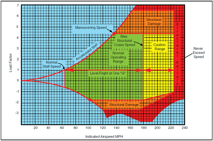
Figure 4: Typical Vg diagram. The diagram is called a Vg diagram—velocity versus “g” loads or load factor. Each airplane has its own Vg diagram which is valid at a certain weight and altitude. The lines of maximum lift capability (curved lines) are the first items of importance on the Vg diagram. The subject airplane in the illustration is capable of developing no more than one positive “g” at 62 m.p.h., the wing level stall speed of the airplane. Since the maximum load factor varies with the square of the airspeed, the maximum positive lift capability of this airplane is 2 “g” at 92 m.p.h., 3 “g” at 112 m.p.h., 4.4 “g” at 137 m.p.h., and so forth. Any load factor above this line is unavailable aerodynamically; i.e., the subject airplane cannot fly above the line of maximum lift capability (it will stall). Essentially the same situation exists for negative lift flight with the exception that the speed necessary to produce a given negative load factor is higher than that to produce the same positive load factor. If the subject airplane is flown at a positive load factor greater than the positive limit load factor of 4.4, structural damage will be possible. When the airplane is operated in this region, objectionable permanent deformation of the primary structure may take place and a high rate of fatigue damage is incurred. Operation above the limit load factor must be avoided in normal operation. There are two other points of importance on the Vg diagram. First, is the intersection of the positive limit load factor and the line of maximum positive lift capability. The airspeed at this point is the minimum airspeed at which the limit load can be developed aerodynamically. Any airspeed greater than this provides a positive lift capability sufficient to damage the airplane; any airspeed less does not provide positive lift capability sufficient to cause damage from excessive flight loads. The usual term given to this speed is “maneuvering speed,” since consideration of subsonic aerodynamics would predict minimum usable turn radius to occur at this condition. The maneuver speed is a valuable reference point, since an airplane operating below this point cannot produce a damaging positive flight load. Any combination of maneuver and gust cannot create damage due to excess airload when the airplane is below the maneuver speed. Next, is the intersection of the negative limit load factor and line of maximum negative lift capability. Any airspeed greater than this provides a negative lift capability sufficient to damage the airplane; any airspeed less does not provide negative lift capability sufficient to damage the airplane from excessive flight loads. The limit airspeed (or redline speed) is a design reference point for the airplane—the subject airplane is limited to 225 m.p.h. If flight is attempted beyond the limit airspeed, structural damage or structural failure may result from a variety of phenomena. Thus, the airplane in flight is limited to a regime of airspeeds and g’s which do not exceed the limit (or redline) speed, do not exceed the limit load factor, and cannot exceed the maximum lift capability. The airplane must be operated within this “envelope” to prevent structural damage and ensure that the anticipated service lift of the airplane is obtained. The pilot must appreciate the Vg diagram as describing the allowable combination of airspeeds and load factors for safe operation. Any maneuver, gust, or gust plus maneuver outside the structural envelope can cause structural damage and effectively shorten the service life of the airplane. This concludes the Load Factors page. You can now go on to the Weight and Balance page or try the FAA Principles of Flight Test. |