


Practical Navigation PrinciplesEffect of wind The preceding discussion on the Navigation Basics page explained how to measure a true course on the aeronautical chart and how to make corrections for variation and deviation, but one important factor has not been considered—wind. As discussed in the study of the atmosphere, wind is a mass of air moving over the surface of the Earth in a definite direction. When the wind is blowing from the north at 25 knots, it simply means that air is moving southward over the Earth’s surface at the rate of 25 nautical miles (NM) in 1 hour. Under these conditions, any inert object free from contact with the Earth will be carried 25 NM southward in 1 hour. This effect becomes apparent when such things as clouds, dust, and toy balloons are observed being blown along by the wind. Obviously, an airplane flying within the moving mass of air will be similarly affected. Even though the airplane does not float freely with the wind, it moves through the air at the same time the air is moving over the ground, thus is affected by wind. Consequently, at the end of 1 hour of flight, the airplane will be in a position which results from a combination of these two motions:
Actually, these two motions are independent. So far as the airplane’s flight through the air is concerned, it makes no difference whether the mass of air through which the airplane is flying is moving or is stationary. A pilot flying in a 70-knot gale would be totally unaware of any wind (except for possible turbulence) unless the ground were observed. In reference to the ground, however, the airplane would appear to fly faster with a tailwind or slower with a headwind, or to drift right or left with a crosswind.
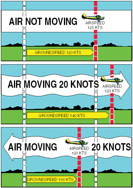
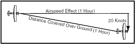
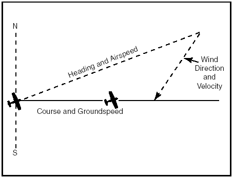
Figure 1: Motion of the air affects the speed with which airplanes move over the Earth’s surface. Airspeed, the rate at which an airplane moves through the air, is not affected by air motion. As shown in figure 1, an airplane flying eastward at an airspeed of 120 knots in still air, will have a groundspeed exactly the same—120 knots. If the mass of air is moving eastward at 20 knots, the airspeed of the airplane will not be affected, but the progress of the airplane over the ground will be 120 plus 20, or a groundspeed of 140 knots. On the other hand, if the mass of air is moving westward at 20 knots, the airspeed of the airplane still remains the same, but groundspeed becomes 120 minus 20 or 100 knots. Assuming no correction is made for wind effect, if the airplane is heading eastward at 120 knots, and the air mass moving southward at 20 knots, the airplane at the end of 1 hour will be almost 120 miles east of its point of departure because of its progress through the air. It will be 20 miles south because of the motion of the air. Under these circumstances, the airspeed remains 120 knots, but the groundspeed is determined by combining the movement of the airplane with that of the air mass. Groundspeed can be measured as the distance from the point of departure to the position of the airplane at the end of 1 hour. The groundspeed can be computed by the time required to fly between two points a known distance apart. It also can be determined before flight by constructing a wind triangle, which will be explained later on this page.
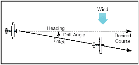
Figure 2: Airplane flightpath resulting from its airspeed and direction, and the windspeed and direction. The direction in which the plane is pointing as it flies is heading. Its actual path over the ground, which is a combination of the motion of the airplane and the motion of the air, is track. The angle between the heading and the track is drift angle. If the airplane’s heading coincides with the true course and the wind is blowing from the left, the track will not coincide with the true course. The wind will drift the airplane to the right, so the track will fall to the right of the desired course or true course.
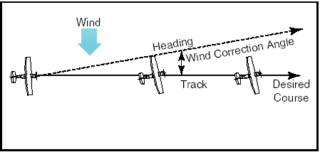
Figure 3: Effects of wind drift on maintaining desired course. By determining the amount of drift, the pilot can counteract the effect of the wind and make the track of the airplane coincide with the desired course. If the mass of air is moving across the course from the left, the airplane will drift to the right, and a correction must be made by heading the airplane sufficiently to the left to offset this drift. To state in another way, if the wind is from the left, the correction will be made by pointing the airplane to the left a certain number of degrees, therefore correcting for wind drift. This is wind correction angle and is expressed in terms of degrees right or left of the true course.
Figure 4: Establishing a wind correction angle that will counteract wind drift and maintain the desired course. To summarize: Course—is the intended path of an airplane over the ground; or the direction of a line drawn on a chart representing the intended airplane path, expressed as the angle measured from a specific reference datum clockwise from 0° through 360° to the line. Heading—is the direction in which the nose of the airplane points during flight. Track—is the actual path made over the ground in flight. (If proper correction has been made for the wind, track and course will be identical.) Drift angle—is the angle between heading and track. Wind correction angle—is correction applied to the course to establish a heading so that track will coincide with course. Airspeed—is the rate of the airplane’s progress through the air. Groundspeed—is the rate of the airplane’s in-flight progress over the ground. Pilotage Pilotage is navigation by reference to landmarks or checkpoints. It is a method of navigation that can be used on any course that has adequate checkpoints, but it is more commonly used in conjunction with dead reckoning and VFR radio navigation. The checkpoints selected should be prominent features common to the area of the flight. Choose checkpoints that can be readily identified by other features such as roads, rivers, railroad tracks, lakes, and power lines. If possible, select features that will make useful boundaries or brackets on each side of the course, such as highways, rivers, railroads, and mountains. A pilot can keep from drifting too far off course by referring to and not crossing the selected brackets. Never place complete reliance on any single checkpoint. Choose ample checkpoints. If one is missed, look for the next one while maintaining the heading. When determining position from checkpoints, remember that the scale of a sectional chart is 1 inch = 8 statute miles or 6.86 nautical miles. For example, if a checkpoint selected was approximately one-half inch from the course line on the chart, it is 4 statue miles or 3.43 nautical miles from the course on the ground. In the more congested areas, some of the smaller features are not included on the chart. If confused, hold the heading. If a turn is made away from the heading, it will be easy to become lost. Roads shown on the chart are primarily the well-traveled roads or those most apparent when viewed from the air. New roads and structures are constantly being built, and may not be shown on the chart until the next chart is issued. Some structures, such as antennas may be difficult to see. Sometimes TV antennas are grouped together in an area near a town. They are supported by almost invisible guy wires. Never approach an area of antennas less than 500 feet above the tallest one. Most of the taller structures are marked with strobe lights to make them more visible to a pilot. However, some weather conditions or background lighting may make them difficult to see. Aeronautical charts display the best information available at the time of printing, but a pilot should be cautious for new structures or changes that have occurred since the chart was printed. Dead reckoning Dead reckoning is navigation solely by means of computations based on time, airspeed, distance, and direction. The products derived from these variables, when adjusted by windspeed and velocity, are heading and groundspeed. The predicted heading will guide the airplane along the intended path and the groundspeed will establish the time to arrive at each checkpoint and the destination. Except for flights over water, dead reckoning is usually used with pilotage for cross-country flying. The heading and groundspeed as calculated is constantly monitored and corrected by pilotage as observed from checkpoints. The wind triangle or vector analysis If there is no wind, the airplane’s ground track will be the same as the heading and the groundspeed will be the same as the true airspeed. This condition rarely exists. A wind triangle, the pilot’s version of vector analysis, is the basis of dead reckoning. The wind triangle is a graphic explanation of the effect of wind upon flight. Groundspeed, heading, and time for any flight can be determined by using the wind triangle. It can be applied to the simplest kind of cross-country flight as well as the most complicated instrument flight. The experienced pilot becomes so familiar with the fundamental principles that estimates can be made which are adequate for visual flight without actually drawing the diagrams. The beginning student, however, needs to develop skill in constructing these diagrams as an aid to the complete understanding of wind effect. Either consciously or unconsciously, every good pilot thinks of the flight in terms of wind triangle.
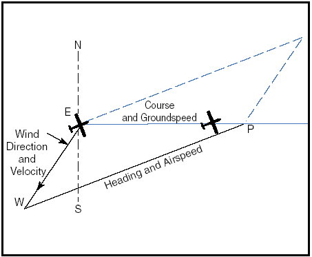
Figure 5: Principle of the wind triangle. If a flight is to be made on a course to the east, with a wind blowing from northeast, the airplane must be headed somewhat to the north of east to counteract drift. This can be represented by a diagram as shown in figure 5. Each line represents direction and speed. The long dotted line shows the direction the plane is heading, and its length represents the airspeed for 1 hour. The short dotted line at the right shows the wind direction, and its length represents the wind velocity for 1 hour. The solid line shows the direction of the track, or the path of the airplane as measured over the Earth, and its length represents the distance traveled in 1 hour, or the groundspeed. In actual practice, the triangle illustrated in figure 5 is not drawn; instead, construct a similar triangle as shown by the black lines in figure 6, which is explained in the following example.
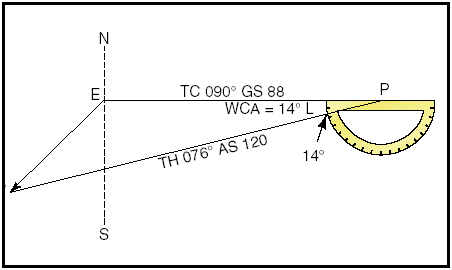
Figure 6: The wind triangle as is drawn in navigation practice. Dashed lines show the triangle as drawn in figure 5. Suppose a flight is to be flown from E to P. Draw a line on the aeronautical chart connecting these two points; measure its direction with a protractor, or plotter, in reference to a meridian. This is the true course, which in this example is assumed to be 090° (east). From the National Weather Service, it is learned that the wind at the altitude of the intended flight is 40 knots from the northeast (045°). Since the National Weather Service reports the windspeed in knots, if the true airspeed of the airplane is 120 knots, there is no need to convert speeds from knots to miles per hour or vice versa. Now on a plain sheet of paper draw a vertical line representing north and south. (The various steps are shown in figure 7.)
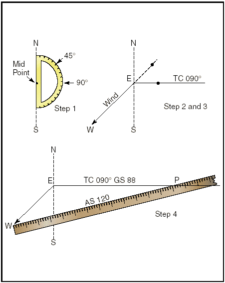
Figure 7: Steps in drawing the wind triangle. Place the protractor with the base resting on the vertical line and the curved edge facing east. At the center point of the base, make a dot labeled “E” (point of departure), and at the curved edge, make a dot at 90° (indicating the direction of the true course) and another at 45° (indicating wind direction). With the ruler, draw the true course line from E, extending it somewhat beyond the dot by 90°, and labeling it “TC 090°.” Next, align the ruler with E and the dot at 45°, and draw the wind arrow from E, not toward 045°, but downwind in the direction the wind is blowing, making it 40 units long, to correspond with the wind velocity of 40 knots. Identify this line as the wind line by placing the letter “W” at the end to show the wind direction. Finally, measure 120 units on the ruler to represent the airspeed, making a dot on the ruler at this point. The units used may be of any convenient scale or value (such as 1/4 inch = 10 knots), but once selected, the same scale must be used for each of the linear movements involved. Then place the ruler so that the end is on the arrowhead (W) and the 120-knot dot intercepts the true course line. Draw the line and label it “AS 120.” The point “P” placed at the intersection represents the position of the airplane at the end of 1 hour. The diagram is now complete. The distance flown in 1 hour (groundspeed) is measured as the numbers of units on the true course line (88 nautical miles per hour or 88 knots). The true heading necessary to offset drift is indicated by the direction of the airspeed line, which can be determined in one of two ways: • By placing the straight side of the protractor along the north-south line, with its center point at the intersection of the airspeed line and northsouth line, read the true heading directly in degrees (076°).
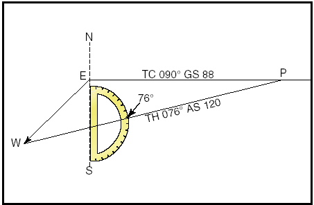
Figure 8: Finding true heading by direct measurement. • By placing the straight side of the protractor along the true course line, with its center at P, read the angle between the true course and the airspeed line. This is the wind correction angle (WCA) which must be applied to the true course to obtain the true heading. If the wind blows from the right of true course, the angle will be added; if from the left, it will be subtracted. In the example given, the WCA is 14° and the wind is from the left; therefore, subtract 14° from true course of 090°, making the true heading 076°.
Figure 9: Finding true heading by the wind correction angle. After obtaining the true heading, apply the correction for magnetic variation to obtain magnetic heading, and the correction for compass deviation to obtain a compass heading. The compass heading can be used to fly to the destination by dead reckoning. To determine the time and fuel required for the flight, first find the distance to destination by measuring the length of the course line drawn on the aeronautical chart (using the appropriate scale at the bottom of the chart). If the distance measures 220 NM, divide by the groundspeed of 88 knots, which gives 2.5 hours or ( True course—Direction of the line connecting two desired points, drawn on the chart and measured clockwise in degrees from true north on the mid-meridian. Wind correction angle—Determined from the wind triangle. (Added to TC if the wind is from the right; subtract if wind is from the left.) True heading—The direction measured in degrees clockwise from true north, in which the nose of the plane should point to make good the desired course. Variation—Obtained from the isogonic line on the chart. (Added to TH if west; subtract if east.) Magnetic heading—An intermediate step in the conversion. (Obtained by applying variation to true heading.) Deviation—Obtained from the deviation card on the airplane. (Added to MH or subtracted from, as indicated.) Compass heading—The reading on the compass (found by applying deviation to MH) which will be followed to make good the desired course. Total distance—Obtained by measuring the length of the TC line on the chart (using the scale at the bottom of the chart). Groundspeed—Obtained by measuring the length of the TC line on the wind triangle (using the scale employed for drawing the diagram). Estimated time en route (ETE)—Total distance divided by groundspeed. Fuel rate—Predetermined gallons per hour used at cruising speed. NOTE: Additional fuel for adequate reserve should be added as a safety measure. Radio navigation Advances in navigational radio receivers installed in airplanes, the development of aeronautical charts which show the exact location of ground transmitting stations and their frequencies, along with refined cockpit instrumentation make it possible for pilots to navigate with precision to almost any point desired. Although precision in navigation is obtainable through the proper use of this equipment, beginning pilots should use this equipment to supplement navigation by visual reference to the ground (pilotage). This method provides the pilot with an effective safeguard against disorientation in the event of radio malfunction. There are four radio navigation systems available for use for VFR navigation. These are:
Very high frequency (VHF) Omnidirectional Range (VOR) The VOR system is present in three slightly different navigation aids (NAVAIDs): VOR, VOR/DME, and VORTAC. By itself it is known as a VOR, and it provides magnetic bearing information to and from the station. When DME is also installed with a VOR, the NAVAID is referred to as a VOR/DME. When military tactical air navigation (TACAN) equipment is installed with a VOR, the NAVAID is known as a VORTAC. DME is always an integral part of a VORTAC. Regardless of the type of NAVAID utilized (VOR, VOR/DME or VORTAC), the VOR indicator behaves the same. Unless otherwise noted, in this section, VOR, VOR/DME and VORTAC NAVAIDs will all be referred to hereafter as VORs. The word “omni” means all, and an omnidirectional range is a VHF radio transmitting ground station that projects straight line courses (radials) from the station in all directions. From a top view, it can be visualized as being similar to the spokes from the hub of a wheel. The distance VOR radials are projected depends upon the power output of the transmitter. The course or radials projected from the station are referenced to magnetic north. Therefore, a radial is defined as a line of magnetic bearing extending outward from the VOR station. Radials are identified by numbers beginning with 001, which is 1° east of magnetic north, and progress in sequence through all the degrees of a circle until reaching 360. To aid in orientation, a compass rose reference to magnetic north is superimposed on aeronautical charts at the station location. VOR ground stations transmit within a VHF frequency band of 108.0 – 117.95 MHz. Because the equipment is VHF, the signals transmitted are subject to line-of-sight restrictions. Therefore, its range varies in direct proportion to the altitude of receiving equipment. Generally, the reception range of the signals at an altitude of 1,000 feet above ground level (AGL) is about 40 to 45 miles. This distance increases with altitude.
Figure 10: VHF transmissions follow a line-of-sight course. VORs and VORTACs are classed according to operational use. There are three classes:
The normal useful range for the various classes is shown in the following table:
The useful range of certain facilities may be less than 50 miles. For further information concerning these restrictions, refer to the Comm/NAVAID Remarks in the Airport/Facility Directory. The accuracy of course alignment of VOR radials is considered to be excellent. It is generally within plus or minus 1°. However, certain parts of the VOR receiver equipment deteriorate, and this affects its accuracy. This is particularly true at great distances from the VOR station. The best assurance of maintaining an accurate VOR receiver is periodic checks and calibrations. VOR accuracy checks are not a regulatory requirement for VFR flight. However, to assure accuracy of the equipment, these checks should be accomplished quite frequently along with a complete calibration each year. The following means are provided for pilots to check VOR accuracy:
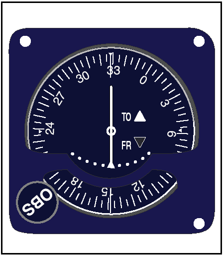
If dual VOR is installed in the airplane and tuned to the same VOR ground facility, the maximum permissible variation between the two indicated bearings is 4°. A list of these checkpoints is published in the Airport/Facility Directory. Basically, these checks consist of verifying that the VOR radials the airplane equipment receives are aligned with the radials the station transmits. There are not specific tolerances in VOR checks required for VFR flight. But as a guide to assure acceptable accuracy, the required IFR tolerances can be used which are ±4° for ground checks and ±6° for airborne checks. These checks can be performed by the pilot. The VOR transmitting station can be positively identified by its Morse code identification or by a recorded voice identification which states the name of the station followed by the word “VOR.” Many Flight Service Stations transmit voice messages on the same frequency that the VOR operates. Voice transmissions should not be relied upon to identify stations, because many FSSs remotely transmit over several omniranges, which have different names than the transmitting FSS. If the VOR is out of service for maintenance, the coded identification is removed and not transmitted. This serves to alert pilots that this station should not be used for navigation. VOR receivers are designed with an alarm flag to indicate when signal strength is inadequate to operate the navigational equipment. This happens if the airplane is too far from the VOR or the airplane is too low and therefore, is out of the line-of-sight of the transmitting signals. Using the VOR In review, for VOR radio navigation, there are two components required: the ground transmitter and the airplane receiving equipment. The ground transmitter is located at a specific position on the ground and transmits on an assigned frequency. The airplane equipment includes a receiver with a tuning device and a VOR or omninavigation instrument. The navigation instrument consists of (1) an omnibearing selector (OBS) sometimes referred to as the course selector, (2) a course deviation indicator needle (Left-Right Needle), and (3) a TO-FROM indicator. The course selector is an azimuth dial that can be rotated to select a desired radial or to determine the radial over which the airplane is flying. In addition, the magnetic course “TO” or “FROM” the station can be determined. When the course selector is rotated, it moves the course deviation indicator (CDI) or needle to indicate the position of the radial relative to the airplane. If the course selector is rotated until the deviation needle is centered, the radial (magnetic course “FROM” the station) or its reciprocal (magnetic course “TO” the station) can be determined. The course deviation needle will also move to the right or left if the airplane is flown or drifting away from the radial which is set in the course selector. By centering the needle, the course selector will indicate either the course “FROM” the station or the course “TO” the station. If the flag displays a “TO,” the course shown on the course selector must be flown to the station.
Figure 11: VOR indicator. If “FROM” is displayed and the course shown is followed, the airplane will be flown away from the station. Tracking with VOR The following describes a step-by-step procedure to use when tracking to and from a VOR station. Figure 12 illustrates the discussion:
Figure 12: Tracking a radial in a crosswind. First, tune the VOR receiver to the frequency of the selected VOR station. For example: 115.0 to receive Bravo VOR. Next, check the identifiers to verify that the desired VOR is being received. As soon as the VOR is properly tuned, the course deviation needle will deflect either left or right; then rotate the azimuth dial to the course selector until the course deviation needle centers and the TO-FROM indicates “TO.” If the needle centers with a “FROM” indication, the azimuth should be rotated 180° because, in this case, it is desired to fly “TO” the station. Now, turn the airplane to the heading indicated on the VOR azimuth dial or course selector. In this example 350°. If a heading of 350° is maintained with a wind from the right as shown, the airplane will drift to the left of the intended track. As the airplane drifts off course, the VOR course deviation needle will gradually move to the right of center or indicate the direction of the desired radial or track. To return to the desired radial, the airplane heading must be altered to the right. As the airplane returns to the desired track, the deviation needle will slowly return to center. When centered, the airplane will be on the desired radial and a left turn must be made toward, but not to the original heading of 350° because a wind drift correction must be established. The amount of correction depends upon the strength of the wind. If the wind velocity is unknown, a trial and error method can be used to find the correct heading. Assume, for this example, a 10° correction or a heading of 360° is maintained. While maintaining a heading of 360°, assume that the course deviation begins to move to the left. This means that the wind correction of 10° is too great and the airplane is flying to the right of course. A slight turn to the left should be made to permit the airplane to return to the desired radial. When the deviation needle centers, a small wind drift correction of 5° or a heading correction of 355° should be flown. If this correction is adequate, the airplane will remain on the radial. If not, small variation in heading should be made to keep the needle centered, and consequently keep the airplane on the radial. As the VOR station is passed, the course deviation needle will fluctuate, then settle down, and the “TO” indication will change to “FROM.” If the airplane passes to one side of the station, the needle will deflect in the direction of the station as the indicator changes to “FROM.” Generally, the same techniques apply when tracking outbound as those used for tracking inbound. If the intent is to fly over the station and track outbound on the reciprocal of the inbound radial, the course selector should not be changed. Corrections are made in the same manner to keep the needle centered. The only difference is that the omni will indicate “FROM.” If tracking outbound on a course other than the reciprocal of the inbound radial, this new course or radial must be set in the course selector and a turn made to intercept this course. After this course is reached, tracking procedures are the same as previously discussed. Tips on using the VOR
Distance measuring equipment Distance measuring equipment (DME) is an ultra high frequency (UHF) navigational aid present with VOR/DMEs and VORTACs. It measures, in nautical miles (NM), the slant range distance of an airplane from a VOR/DME or VORTAC (both hereafter referred to as a VORTAC). Although DME equipment is very popular, not all airplanes are DME equipped. To utilize DME, the pilot should select, tune, and identify a VORTAC, as previously described. The DME receiver, utilizing what is called a “paired frequency” concept, automatically selects and tunes the UHF DME frequency associated with the VHF VORTAC frequency selected by the pilot. This process is entirely transparent to the pilot. After a brief pause, the DME display will show the slant range distance to or from the VORTAC. Slant range distance is the direct distance between the airplane and the VORTAC, and is therefore affected by airplane altitude. (Station passage directly over a VORTAC from an altitude of 6,076 feet above ground level (AGL) would show approximately 1.0 NM on the DME.) DME is a very useful adjunct to VOR navigation. A VOR radial alone merely gives line of position information. With DME, a pilot may precisely locate the airplane on that line (radial). Most DME receivers also provide groundspeed and time-to-station modes of operation. The groundspeed is displayed in knots (NM per hour). The time-to-station mode displays the minutes remaining to VORTAC station passage, predicated upon the present groundspeed. Groundspeed and time-to-station information is only accurate when tracking directly to or from a VORTAC. DME receivers typically need a minute or two of stabilized flight directly to or from a VORTAC before displaying accurate groundspeed or time-to-station information. Some DME installations have a hold feature that permits a DME signal to be retained from one VORTAC while the course indicator displays course deviation information from an ILS or another VORTAC. VOR/DME RNAV Area navigation (RNAV) permits electronic course guidance on any direct route between points established by the pilot. While RNAV is a generic term that applies to a variety of navigational aids, such as LORAN-C, GPS, and others, this section will deal with VOR/DME-based RNAV. VOR/DME RNAV is not a separate ground-based NAVAID, but a method of navigation using VOR/DME and VORTAC signals specially processed by the airplane’s RNAV computer.
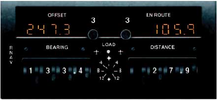
FIGURE 13: Flying an RNAV course. Note: In this section, the term “VORTAC” also includes VOR/DME NAVAIDs. In its simplest form, VOR/DME RNAV allows the pilot to electronically move VORTACs around to more convenient locations. Once electronically relocated, they are referred to as waypoints. These waypoints are described as a combination of a selected radial and distance within the service volume of the VORTAC to be used. These waypoints allow a straight course to be flown between almost any origin and destination, without regard to the orientation of VORTACs or the existence of airways. While the capabilities and methods of operation of VOR/DME RNAV units differ, there are basic principals of operation that are common to all. Pilots are urged to study the manufacturer’s operating guide and receive instruction prior to the use of VOR/DME RNAV or any unfamiliar navigational system. Operational information and limitations should also be sought from placards and the supplement section of the Airplane Flight Manual and/or Pilot’s Operating Handbook (AFM/POH). VOR/DME-based RNAV units operate in at least three modes: VOR, En Route, and Approach. A fourth mode, VOR Parallel, may also be found on some models. The units need both VOR and DME signals to operate in any RNAV mode. If the NAVAID selected is a VOR without DME, RNAV mode will not function. In the VOR (or non-RNAV) mode, the unit simply functions as a VOR receiver with DME capability.
FIGURE 14: RNAV controls. The unit’s display on the VOR indicator is conventional in all respects. For operation on established airways or any other ordinary VOR navigation, the VOR mode is used. To utilize the unit’s RNAV capability, the pilot selects and establishes a waypoint or a series of waypoints to define a course. To operate in any RNAV mode, the unit needs both radial and distance signals; therefore, a VORTAC (or VOR/DME) needs to be selected as a NAVAID. To establish a waypoint, a point somewhere within the service range of a VORTAC is defined on the basis of radial and distance. Once the waypoint is entered into the unit and the RNAV En Route mode is selected, the CDI will display course guidance to the waypoint, not the original VORTAC. DME will also display distance to the waypoint. Many units have the capability to store several waypoints, allowing them to be programmed prior to flight, if desired, and called up in flight. RNAV waypoints are entered into the unit in magnetic bearings (radials) of degrees and tenths (i.e., 275.5°) and distances in nautical miles and tenths (i.e., 25.2 NM). When plotting RNAV waypoints on an aeronautical chart, pilots will find it difficult to measure to that level of accuracy, and in practical application, it is rarely necessary. A number of flight planning publications publish airport coordinates and waypoints with this precision and the unit will accept those figures. There is a subtle, but important difference in CDI operation and display in the RNAV modes. In the RNAV modes, course deviation is displayed in terms of linear deviation. In the RNAV En Route mode, maximum deflection of the CDI typically represents 5 NM on either side of the selected course, without regard to distance from the waypoint. In the RNAV Approach mode, maximum deflection of the CDI typically represents 1 1/4 NM on either side of the selected course. There is no increase in CDI sensitivity as the airplane approaches a waypoint in RNAV mode. The RNAV Approach mode is used for instrument approaches. Its narrow scale width (one-quarter of the En Route mode) permits very precise tracking to or from the selected waypoint. In visual flight rules (VFR) cross-country navigation, tracking a course in the Approach mode is not desirable because it requires a great deal of attention and soon becomes tedious. A fourth, lesser-used mode on some units is the VOR Parallel mode. This permits the CDI to display linear (not angular) deviation as the airplane tracks to and from VORTACs. It derives its name from permitting the pilot to offset (or parallel) a selected course or airway at a fixed distance of the pilot’s choosing, if desired. The VOR Parallel mode has the same effect as placing a waypoint directly over an existing VORTAC. Some pilots select the VOR Parallel mode when utilizing the navigation (NAV) tracking function of their autopilot for smoother course following near the VORTAC. Confusion is possible when navigating an airplane with VOR/DME-based RNAV, and it is essential that the pilot become familiar with the equipment installed. It is not unknown for pilots to operate inadvertently in one of the RNAV modes when the operation was not intended by overlooking switch positions or annunciators. The reverse has also occurred with a pilot neglecting to place the unit into one of the RNAV modes by overlooking switch positions or annunciators. As always, the prudent pilot is not only familiar with the equipment used, but never places complete reliance in just one method of navigation when others are available for cross-check. Automatic direction finder Many general aviation-type airplanes are equipped with automatic direction finder (ADF) radio receiving equipment. To navigate using the ADF, the pilot tunes the receiving equipment to a ground station known as a NONDIRECTIONAL RADIOBEACON (NDB). The NDB stations normally operate in a low or medium frequency band of 200 to 415 kHz. The frequencies are readily available on aeronautical charts or in the Airport/Facility Directory. All radiobeacons except compass locators transmit a continuous three-letter identification in code except during voice transmissions. A compass locator, which is associated with an Instrument Landing System, transmits a two-letter identification. Standard broadcast stations can also be used in conjunction with ADF. Positive identification of all radio stations is extremely important and this is particularly true when using standard broadcast stations for navigation. Nondirectional radiobeacons have one advantage over the VOR. This advantage is that low or medium frequencies are not affected by line-of-sight. The signals follow the curvature of the Earth; therefore, if the airplane is within the range of the station, the signals can be received regardless of altitude. The following table gives the class of NDB stations, their power, and usable range:
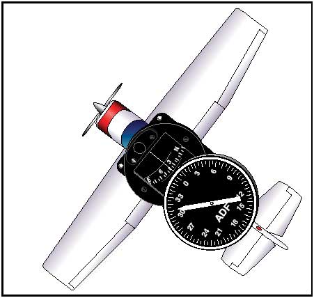
*Service range of individual facilities may be less than 50 miles. One of the disadvantages that should be considered when using low frequency for navigation is that low-frequency signals are very susceptible to electrical disturbances, such as lightning. These disturbances create excessive static, needle deviations, and signal fades. There may be interference from distant stations. Pilots should know the conditions under which these disturbances can occur so they can be more alert to possible interference when using the ADF. Basically, the ADF airplane equipment consists of a tuner, which is used to set the desired station frequency, and the navigational display. The navigational display consists of a dial upon which the azimuth is printed, and a needle which rotates around the dial and points to the station to which the receiver is tuned. Some of the ADF dials can be rotated so as to align the azimuth with the airplane heading; others are fixed with 0° representing the nose of the airplane, and 180° representing the tail. Only the fixed azimuth dial will be discussed here.
Figure 15: ADF with fixed azimuth and magnetic compass.
Figure 16: ADF terms. Figure 16 illustrates the following terms that are used with the ADF and should be understood by the pilot. Relative Bearing—is the value to which the indicator (needle) points on the azimuth dial. When using a fixed dial, this number is relative to the nose of the airplane and is the angle measured clockwise from the nose of the airplane to a line drawn from the airplane to the station. Magnetic Bearing—“TO” the station is the angle formed by a line drawn from the airplane to the station and a line drawn from the airplane to magnetic north. The magnetic bearing to the station can be determined by adding the relative bearing to the magnetic heading of the airplane. For example, if the relative bearing is 060° and the magnetic heading is 130°, the magnetic bearing to the station is 060° plus 130° or 190°. This means that in still air a magnetic heading of approximately 190° would be flown to the station. If the total is greater than 360°, subtract 360° from the total to obtain the magnetic bearing to the station. For example, if the relative bearing is 270° and magnetic heading is 300°, 360° is subtracted from the total, or 570° – 360° = 210°, which is the magnetic bearing to the station. To determine the magnetic bearing “FROM” the station, 180° is added to or subtracted from the magnetic bearing to the station. This is the reciprocal bearing and is used when plotting position fixes. Keep in mind that the needle of fixed azimuth points to the station in relation to the nose of the airplane. If the needle is deflected 30° to the left or a relative bearing of 330°, this means that the station is located 30° left. If the airplane is turned left 30°, the needle will move to the right 30° and indicate a relative bearing of 0° or the airplane will be pointing toward the station. If the pilot continues flight toward the station keeping the needle on 0°, the procedure is called homing to the station. If a crosswind exists, the ADF needle will continue to drift away from zero. To keep the needle on zero, the airplane must be turned slightly resulting in a curved flightpath to the station. Homing to the station is a common procedure, but results in drifting downwind, thus lengthening the distance to the station. Tracking to the station requires correcting for wind drift and results in maintaining flight along a straight track or bearing to the station. When the wind drift correction is established, the ADF needle will indicate the amount of correction to the right or left. For instance, if the magnetic bearing to the station is 340°, a correction for a left crosswind would result in a magnetic heading of 330°, and the ADF needle would indicate 10° to the right or a relative bearing of 010°.
Figure 17: ADF tracking. When tracking away from the station, wind corrections are made similar to tracking to the station, but the ADF needle points toward the tail of the airplane or the 180° position on the azimuth dial. Attempting to keep the ADF needle on the 180° position during winds results in the airplane flying a curved flight leading further and further from the desired track. To correct for wind when tracking outbound, correction should be made in the direction opposite of that in which the needle is pointing. Although the ADF is not as popular as the VOR for radio navigation, with proper precautions and intelligent use, the ADF can be a valuable aid to navigation. LORAN-C navigation Long Range Navigation, version C (LORAN-C) is another form of RNAV, but one that operates from chains of transmitters broadcasting signals in the low frequency (LF) spectrum. World Aeronautical Chart (WAC), Sectional Charts, and VFR Terminal Area Charts do not show the presence of LORAN-C transmitters. Selection of a transmitter chain is either made automatically by the unit, or manually by the pilot using guidance information provided by the manufacturer. LORAN-C is a highly accurate, supplemental form of navigation typically installed as an adjunct to VOR and ADF equipment. Databases of airports, NAVAIDs, and air traffic control facilities are frequently features of LORAN-C receivers. LORAN-C is an outgrowth of the original LORAN-A developed for navigation during World War II. The LORAN-C system is used extensively in maritime applications. It experienced a dramatic growth in popularity with pilots with the advent of the small, panel-mounted LORAN-C receivers available at relatively low cost. These units are frequently very sophisticated and capable, with a wide variety of navigational functions. With high levels of LORAN-C sophistication and capability, a certain complexity in operation is an unfortunate necessity. Pilots are urged to read the operating handbooks and to consult the supplements section of the AFM/POH prior to utilizing LORAN-C for navigation. Many units offer so many features that the manufacturers often publish two different sets of instructions: (1) a brief operating guide and (2) in-depth operating manual. While coverage is not global, LORAN-C signals are suitable for navigation in all of the conterminous United States, and parts of Canada and Alaska. Several foreign countries also operate their own LORAN-C systems. In the United States, the U.S. Coast Guard operates the LORAN-C system. LORAN-C system status is available from: USCG Navigation Center, Alexandria, VA (703) 313-5900. LORAN-C absolute accuracy is excellent—position errors are typically less than .25 NM. Repeatable accuracy, or the ability to return to a waypoint previously visited, is even better. While LORAN-C is a form of RNAV, it differs significantly from VOR/DME-based RNAV. It operates in a 90 – 110 kHz frequency range and is based upon measurement of the difference in arrival times of pulses of radio frequency (RF) energy emitted by a chain of transmitters hundreds of miles apart. Within any given chain of transmitters, there is a master station, and from three to five secondary stations. LORAN-C units must be able to receive at least a master and two secondary stations to provide navigational information. Unlike VOR/DME-based RNAV, where the pilot must select the appropriate VOR/DME or VORTAC frequency, there is not a frequency selection in LORAN-C. The most advanced units automatically select the optimum chain for navigation. Other units rely upon the pilot to select the appropriate chain with a manual entry. After the LORAN-C receiver has been turned on, the unit must be initialized before it can be used for navigation. While this can be accomplished in flight, it is preferable to perform this task, which can take several minutes, on the ground. The methods for initialization are as varied as the number of different models of receivers. Some require pilot input during the process, such as verification or acknowledgment of the information displayed. Most units contain databases of navigational information. Frequently, such databases contain not only airport and NAVAID locations, but also extensive airport, airspace, and ATC information. While the unit will operate with an expired database, the information should be current or verified to be correct prior to use. The pilot can update some databases, while others require removal from the airplane and the services of an avionics technician. VFR navigation with LORAN-C can be as simple as telling the unit where the pilot wishes to go. The course guidance provided will be a great circle (shortest distance) route to the destination. Older units may need a destination entered in terms of latitude and longitude, but recent designs only need the identifier of the airport or NAVAID. The unit will also permit database storage and retrieval of pilot defined waypoints. LORAN-C signals follow the curvature of the Earth and are generally usable hundreds of miles from their transmitters. The LORAN-C signal is subject to degradation from a variety of atmospheric disturbances. It is also susceptible to interference from static electricity buildup on the airframe and electrically “noisy” airframe equipment. Flight in precipitation or even dust clouds can cause occasional interference with navigational guidance from LORAN-C signals. To minimize these effects, static wicks and bonding straps should be installed and properly maintained. LORAN-C navigation information is presented to the pilot in a variety of ways. All units have self-contained displays, and some elaborate units feature built-in moving map displays. Some installations can also drive an external moving map display, a conventional VOR indicator, or a horizontal situation indicator (HSI). Course deviation information is presented as a linear deviation from course—there is no increase in tracking sensitivity as the airplane approaches the waypoint or destination. Pilots must carefully observe placards, selector switch positions, and annunciator indications when utilizing LORAN-C because airplane installations can vary widely. The pilot’s familiarity with unit operation through AFM/POH supplements and operating guides cannot be overemphasized. LORAN-C Notices To Airmen (NOTAMs) should be reviewed prior to relying on LORAN-C for navigation. LORAN-C NOTAMs will be issued to announce outages for specific chains and transmitters. Pilots may obtain LORAN-C NOTAMs from FSS briefers only upon request. The prudent pilot will never rely solely on one means of navigation when others are available for backup and cross-check. Pilots should never become so dependent upon the extensive capabilities of LORAN-C that other methods of navigation are neglected. Global positioning system The global positioning system (GPS) is a satellite based radio navigation system. Its RNAV guidance is worldwide in scope. There are no symbols for GPS on aeronautical charts as it is a space-based system with global coverage. Development of the system is underway so that GPS will be capable of providing the primary means of electronic navigation. Portable and yoke mounted units are proving to be very popular in addition to those permanently installed in the airplane. Extensive navigation databases are common features in airplane GPS receivers. The GPS is a satellite radio navigation and time dissemination system developed and operated by the U.S. Department of Defense (DOD). Civilian interface and GPS system status is available from the U.S. Coast Guard. It is not necessary to understand the technical aspects of GPS operation to use it in VFR/instrument flight rules (IFR) navigation. It does differ significantly from conventional, ground-based electronic navigation, and awareness of those differences is important. Awareness of equipment approvals and limitations is critical to the safety of flight. The GPS system is composed of three major elements:
To solve for its location, the GPS receiver utilizes the signals of at least four of the best-positioned satellites to yield a three-dimensional fix (latitude, longitude, and altitude). A two-dimensional fix (latitude and longitude only) can be determined with as few as three satellites. GPS receivers have extensive databases. Databases are provided initially by the receiver manufacturer and updated by the manufacturer or a designated data agency. A wide variety of GPS receivers with extensive navigation capabilities are available. Panel mounted units permanently installed in the airplane may be used for VFR and may also have certain IFR approvals. Portable hand-held and yoke mounted GPS receivers are also popular, although these are limited to VFR use. Not all GPS receivers on the market are suited for air navigation. Marine, recreational, and surveying units, for example, are not suitable for airplane use. As with LORAN-C receivers, GPS unit features and operating procedures vary widely. The pilot must be familiar with the manufacturer’s operating guide. Placards, switch positions, and annunciators should be carefully observed. Initialization of the unit will require several minutes and should be accomplished prior to flight. If the unit has not been operated for several months or if it has been moved to a significantly different location (by several hundred miles) while off, this may require several additional minutes. During initialization, the unit will make internal integrity checks, acquire satellite signals, and display the database revision date. While the unit will operate with an expired database, the database should be current, or verified to be correct, prior to relying on it for navigation. VFR navigation with GPS can be as simple as selecting a destination (an airport, VOR, NDB, intersection, or pilot defined waypoint) and placing the unit in the navigation mode. Course guidance provided will be a great circle route (shortest distance) direct to the destination. Many units provide advisory information about special use airspace and minimum safe altitudes, along with extensive airport data, and ATC services and frequencies. Users having prior experience with LORAN-C receivers will note many similarities in the wealth of navigation information available, although the technical principles of operation are quite different. All GPS receivers have integral (built into the unit) navigation displays and some feature integral moving map displays. Some panel-mounted units will drive a VOR indicator, HSI, or even an external moving map display. GPS course deviation is linear—there is not an increase in tracking sensitivity as the airplane approaches a waypoint. Pilots must carefully observe placards, selector switch positions, and annunciator indications when utilizing GPS as installations and approvals can vary widely. The integral GPS navigation display (like most LORAN-C units) uses several additional navigational terms beyond those used in NDB and VOR navigation. The pilot should consult the manufacturer’s operating guide for specific definitions. NOTAMs should be reviewed prior to relying on GPS for navigation. GPS NOTAMs will be issued to announce outages for specific GPS satellites by pseudo random noise code (PRN) and satellite vehicle number (SVN). Pilots may obtain GPS NOTAMs from FSS briefers only upon request. When using any sophisticated and highly capable navigation system, such as LORAN-C or GPS, there is a strong temptation to rely almost exclusively on that unit, to the detriment of using other techniques of position keeping. The prudent pilot will never rely on one means of navigation when others are available for cross-check and backup. This concludes the Practical Navigation Principles page. You can now test your knowledge with the FAA Navigation Test question bank |
|||||||||||||||||||||||||||||||||||||||||||||||||