


Propeller aerodynamicsThe airplane propeller consists of two or more blades and a central hub to which the blades are attached. Each blade of an airplane propeller is essentially a rotating wing. As a result of their construction, the propeller blades are like airfoils and produce forces that create the thrust to pull, or push, the airplane through the air. The power needed to rotate the propeller blades is furnished by the engine. The engine rotates the airfoils of the blades through the air at high speeds, and the propeller transforms the rotary power of the engine into forward thrust. An airplane moving through the air creates a drag force opposing its forward motion. Consequently, if an airplane is to fly, there must be a force applied to it that is equal to the drag, but acting forward. This force is called “thrust.”
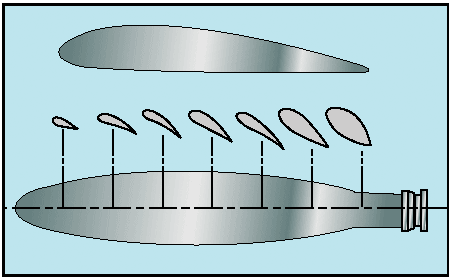
Figure 1: Airfoil sections of propeller blade. A cross section of a typical propeller blade is shown in figure 1. This section or blade element is an airfoil comparable to a cross section of an airplane wing. One surface of the blade is cambered or curved, similar to the upper surface of an airplane wing, while the other surface is flat like the bottom surface of a wing. The chord line is an imaginary line drawn through the blade from its leading edge to its trailing edge. As in a wing, the leading edge is the thick edge of the blade that meets the air as the propeller rotates.
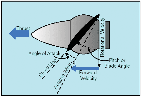
Figure 2: Propeller blade angle. Blade angle, usually measured in degrees, is the angle between the chord of the blade and the plane of rotation and is measured at a specific point along the length of the blade. Because most propellers have a flat blade “face,” the chord line is often drawn along the face of the propeller blade. Pitch is not the same as blade angle, but because pitch is largely determined by blade angle, the two terms are often used interchangeably. An increase or decrease in one is usually associated with an increase or decrease in the other. The pitch of a propeller may be designated in inches. A propeller designated as a “74-48” would be 74 inches in length and have an effective pitch of 48 inches. The pitch in inches is the distance which the propeller would screw through the air in one revolution if there were no slippage. When specifying a fixed-pitch propeller for a new type of airplane, the manufacturer usually selects one with a pitch that will operate efficiently at the expected cruising speed of the airplane. Unfortunately, however, every fixed-pitch propeller must be a compromise, because it can be efficient at only a given combination of airspeed and r.p.m. Pilots do not have it within their power to change this combination in flight. When the airplane is at rest on the ground with the engine operating, or moving slowly at the beginning of takeoff, the propeller efficiency is very low because the propeller is restrained from advancing with sufficient speed to permit its fixed-pitch blades to reach their full efficiency. In this situation, each propeller blade is turning through the air at an angle of attack that produces relatively little thrust for the amount of power required to turn it. To understand the action of a propeller, consider first its motion, which is both rotational and forward. Thus, as shown by the vectors of propeller forces in figure 2, each section of a propeller blade moves downward and forward. The angle at which this air (relative wind) strikes the propeller blade is its angle of attack. The air deflection produced by this angle causes the dynamic pressure at the engine side of the propeller blade to be greater than atmospheric, thus creating thrust. The shape of the blade also creates thrust, because it is cambered like the airfoil shape of a wing. Consequently, as the air flows past the propeller, the pressure on one side is less than that on the other. As in a wing, this produces a reaction force in the direction of the lesser pressure. In the case of a wing, the airflow over the wing has less pressure, and the force (lift) is upward. In the case of the propeller, which is mounted in a vertical instead of a horizontal plane, the area of decreased pressure is in front of the propeller, and the force (thrust) is in a forward direction. Aerodynamically, then, thrust is the result of the propeller shape and the angle of attack of the blade. Another way to consider thrust is in terms of the mass of air handled by the propeller. In these terms, thrust is equal to the mass of air handled, times the slipstream velocity, minus the velocity of the airplane. The power expended in producing thrust depends on the rate of air mass movement. On the average, thrust constitutes approximately 80 percent of the torque (total horsepower absorbed by the propeller). The other 20 percent is lost in friction and slippage. For any speed of rotation, the horsepower absorbed by the propeller balances the horsepower delivered by the engine. For any single revolution of the propeller, the amount of air handled depends on the blade angle, which determines how big a “bite” of air the propeller takes. Thus, the blade angle is an excellent means of adjusting the load on the propeller to control the engine r.p.m. The blade angle is also an excellent method of adjusting the angle of attack of the propeller. On constant-speed propellers, the blade angle must be adjusted to provide the most efficient angle of attack at all engine and airplane speeds. Lift versus drag curves, which are drawn for propellers as well as wings, indicate that the most efficient angle of attack is a small one varying from 2° to 4° positive. The actual blade angle necessary to maintain this small angle of attack varies with the forward speed of the airplane. Fixed-pitch and ground-adjustable propellers are designed for best efficiency at one rotation and forward speed. They are designed for a given airplane and engine combination. A propeller may be used that provides the maximum propeller efficiency for either takeoff, climb, cruise, or high-speed flight. Any change in these conditions results in lowering the efficiency of both the propeller and the engine. Since the efficiency of any machine is the ratio of the useful power output to the actual power input, propeller efficiency is the ratio of thrust horsepower to brake horsepower. Propeller efficiency varies from 50 to 87 percent, depending on how much the propeller “slips.” Propeller slip is the difference between the geometric pitch of the propeller and its effective pitch.
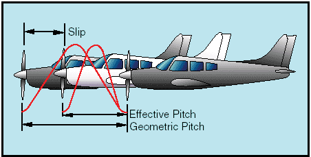
Figure 3: Propeller slippage. Geometric pitch is the theoretical distance a propeller should advance in one revolution; effective pitch is the distance it actually advances. Thus, geometric or theoretical pitch is based on no slippage, but actual or effective pitch includes propeller slippage in the air. The reason a propeller is “twisted” is that the outer parts of the propeller blades, like all things that turn about a central point, travel faster than the portions near the hub.
Figure 4: Propeller tips travel faster than hubs. If the blades had the same geometric pitch throughout their lengths, at cruise speed the portions near the hub could have negative angles of attack while the propeller tips would be stalled. “Twisting,” or variations in the geometric pitch of the blades, permits the propeller to operate with a relatively constant angle of attack along its length when in cruising flight. To put it another way, propeller blades are twisted to change the blade angle in proportion to the differences in speed of rotation along the length of the propeller and thereby keep thrust more nearly equalized along this length. Usually 1° to 4° provides the most efficient lift/drag ratio, but in flight the propeller angle of attack of a fixed-pitch propeller will vary—normally from 0° to 15°. This variation is caused by changes in the relative airstream which in turn results from changes in airplane speed. In short, propeller angle of attack is the product of two motions: propeller rotation about its axis and its forward motion. A constant-speed propeller, however, automatically keeps the blade angle adjusted for maximum efficiency for most conditions encountered in flight. During takeoff, when maximum power and thrust are required, the constant-speed propeller is at a low propeller blade angle or pitch. The low blade angle keeps the angle of attack small and efficient with respect to the relative wind. At the same time, it allows the propeller to handle a smaller mass of air per revolution. This light load allows the engine to turn at high r.p.m. and to convert the maximum amount of fuel into heat energy in a given time. The high r.p.m. also creates maximum thrust; for, although the mass of air handled per revolution is small, the number of revolutions per minute is many, the slipstream velocity is high, and with the low airplane speed, the thrust is maximum. After liftoff, as the speed of the airplane increases, the constant-speed propeller automatically changes to a higher angle (or pitch). Again, the higher blade angle keeps the angle of attack small and efficient with respect to the relative wind. The higher blade angle increases the mass of air handled per revolution. This decreases the engine r.p.m., reducing fuel consumption and engine wear, and keeps thrust at a maximum. After the takeoff climb is established in an airplane having a controllable-pitch propeller, the pilot reduces the power output of the engine to climb power by first decreasing the manifold pressure and then increasing the blade angle to lower the r.p.m. At cruising altitude, when the airplane is in level flight and less power is required than is used in takeoff or climb, the pilot again reduces engine power by reducing the manifold pressure and then increasing the blade angle to decrease the r.p.m. Again, this provides a torque requirement to match the reduced engine power; for, although the mass of air handled per revolution is greater, it is more than offset by a decrease in slipstream velocity and an increase in airspeed. The angle of attack is still small because the blade angle has been increased with an increase in airspeed. Torque and P factor To the pilot, “torque” (the left turning tendency of the airplane) is made up of four elements which cause or produce a twisting or rotating motion around at least one of the airplane’s three axes. These four elements are:
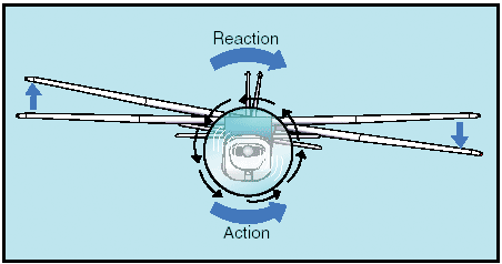
Torque reaction Torque reaction involves Newton’s Third Law of Physics—for every action, there is an equal and opposite reaction. As applied to the airplane, this means that as the internal engine parts and propeller are revolving in one direction, an equal force is trying to rotate the airplane in the opposite direction.
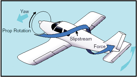
Figure 5: Torque reaction. When the airplane is airborne, this force is acting around the longitudinal axis, tending to make the airplane roll. To compensate for this, some of the older airplanes are rigged in a manner to create more lift on the wing that is being forced downward. The more modern airplanes are designed with the engine offset to counteract this effect of torque. NOTE—Most United States built aircraft engines rotate the propeller clockwise, as viewed from the pilot’s seat. The discussion here is with reference to those engines. Generally, the compensating factors are permanently set so that they compensate for this force at cruising speed, since most of the airplane’s operating lift is at that speed. However, aileron trim tabs permit further adjustment for other speeds. When the airplane’s wheels are on the ground during the takeoff roll, an additional turning moment around the vertical axis is induced by torque reaction. As the left side of the airplane is being forced down by torque reaction, more weight is being placed on the left main landing gear. This results in more ground friction, or drag, on the left tire than on the right, causing a further turning moment to the left. The magnitude of this moment is dependent on many variables. Some of these variables are: (1) size and horsepower of engine, (2) size of propeller and the r.p.m., (3) size of the airplane, and (4) condition of the ground surface. This yawing moment on the takeoff roll is corrected by the pilot’s proper use of the rudder or rudder trim. Corkscrew effect The high-speed rotation of an airplane propeller gives a corkscrew or spiraling rotation to the slipstream. At high propeller speeds and low forward speed (as in the takeoffs and approaches to power on stalls), this spiraling rotation is very compact and exerts a strong sideward force on the airplane’s vertical tail surface.
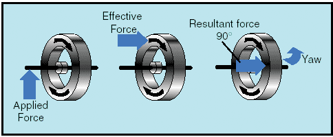
Figure 6: Corkscrewing slipstream. When this spiraling slipstream strikes the vertical fin on the left, it causes a left turning moment about the airplane’s vertical axis. The more compact the spiral, the more prominent this force is. As the forward speed increases, however, the spiral elongates and becomes less effective. The corkscrew flow of the slipstream also causes a rolling moment around the longitudinal axis. Note that this rolling moment caused by the corkscrew flow of the slipstream is to the right, while the rolling moment caused by torque reaction is to the left—in effect one may be counteracting the other. However, these forces vary greatly and it is up to the pilot to apply proper correction action by use of the flight controls at all times. These forces must be counteracted regardless of which is the most prominent at the time. Gyroscopic action Before the gyroscopic effects of the propeller can be understood, it is necessary to understand the basic principle of a gyroscope. All practical applications of the gyroscope are based upon two fundamental properties of gyroscopic action: rigidity in space and precession. The one of interest for this discussion is precession.
Figure 7: Gyroscopic precession. Precession is the resultant action, or deflection, of a spinning rotor when a deflecting force is applied to its rim. As can be seen in figure 7, when a force is applied, the resulting force takes effect 90° ahead of and in the direction of rotation. The rotating propeller of an airplane makes a very good gyroscope and thus has similar properties. Any time a force is applied to deflect the propeller out of its plane of rotation, the resulting force is 90° ahead of and in the direction of rotation and in the direction of application, causing a pitching moment, a yawing moment, or a combination of the two depending upon the point at which the force was applied. This element of torque effect has always been associated with and considered more prominent in tailwheel-type airplanes, and most often occurs when the tail is being raised during the takeoff roll.
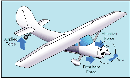
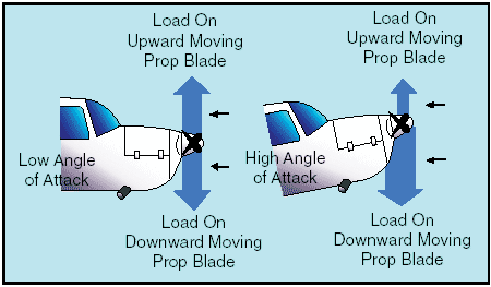
Figure 8: Raising tail produces gyroscopic precession. This change in pitch attitude has the same effect as applying a force to the top of the propeller’s plane of rotation. The resultant force acting 90° ahead causes a yawing moment to the left around the vertical axis. The magnitude of this moment depends on several variables, one of which is the abruptness with which the tail is raised (amount of force applied). However, precession, or gyroscopic action, occurs when a force is applied to any point on the rim of the propeller’s plane of rotation; the resultant force will still be 90° from the point of application in the direction of rotation. Depending on where the force is applied, the airplane is caused to yaw left or right, to pitch up or down, or a combination of pitching and yawing. It can be said that as a result of gyroscopic action—any yawing around the vertical axis results in a pitching moment, and any pitching around the lateral axis results in a yawing moment. To correct for the effect of gyroscopic action, it is necessary for the pilot to properly use elevator and rudder to prevent undesired pitching and yawing. Asymmetric loading (P-factor) When an airplane is flying with a high angle of attack, the “bite” of the downward moving blade is greater than the “bite” of the upward moving blade; thus moving the center of thrust to the right of the prop disc area—causing a yawing moment toward the left around the vertical axis. That explanation is correct; however, to prove this phenomenon, it would be necessary to work wind vector problems on each blade, which gets quite involved when considering both the angle of attack of the airplane and the angle of attack of each blade. This asymmetric loading is caused by the resultant velocity, which is generated by the combination of the velocity of the propeller blade in its plane of rotation and the velocity of the air passing horizontally through the propeller “disc.” With the airplane being flown at positive angles of attack, the right (viewed from the rear) or downswinging blade, is passing through an area of resultant velocity which is greater than that affecting the left or upswinging blade. Since the propeller blade is an airfoil, increased velocity means increased lift. Therefore, the downswinging blade having more “lift” tends to pull (yaw) the airplane’s nose to the left. Simply stated, when the airplane is flying at a high angle of attack, the downward moving blade has a higher resultant velocity; therefore creating more lift than the upward moving blade.
Figure 9: Asymmetrical loading of propeller (P-factor). This might be easier to visualize if the propeller shaft was mounted perpendicular to the ground (like a helicopter). If there were no air movement at all, except that generated by the propeller itself, identical sections of each blade would have the same airspeed. However, with air moving horizontally across this vertically mounted propeller, the blade proceeding forward into the flow of air will have a higher airspeed than the blade retreating with the airflow. Thus, the blade proceeding into the horizontal airflow is creating more lift, or thrust, moving the center of thrust toward that blade. Visualize ROTATING the vertically mounted propeller shaft to shallower angles relative to the moving air (as on an airplane). This unbalanced thrust then becomes proportionately smaller and continues getting smaller until it reaches the value of zero when the propeller shaft is exactly horizontal in relation to the moving air. Each of these four elements of torque effects vary in values with changes in flight situations. In one phase of flight, one of these elements may be more prominent than another; whereas, in another phase of flight, another element may be more prominent. The relationship of these values to each other will vary with different airplanes—depending on the AIRFRAME, ENGINE, AND PROPELLER combinations as well as other design features. To maintain positive control of the airplane in all flight conditions, the pilot must apply the flight controls as necessary to compensate for these varying values. This concludes the propeller aerodynamics page. Please return to the Aircraft Powerplant page to continue study. |