
Aeronautics: influence of airplane design characteristics on stability and handling of aircraft.Airplane design characteristics Every pilot who has flown numerous types of airplanes has noted that each airplane handles somewhat differently—that is, each resists or responds to control pressures in its own way. A training type airplane is quick to respond to control applications, while a transport airplane usually feels heavy on the controls and responds to control pressures more slowly. These features can be designed into an airplane to facilitate the particular purpose the airplane is to fulfill by considering certain stability and maneuvering requirements. In the following discussion, it is intended to summarize the more important aspects of an airplane’s stability; its maneuvering and controllability qualities; how they are analyzed; and their relationship to various flight conditions. In brief, the basic differences between stability, maneuverability, and controllability are as follows: • Stability—The inherent quality of an airplane to correct for conditions that may disturb its equilibrium, and to return or to continue on the original flightpath. It is primarily an airplane design characteristic. • Maneuverability—The quality of an airplane that permits it to be maneuvered easily and to withstand the stresses imposed by maneuvers. It is governed by the airplane’s weight, inertia, size and location of flight controls, structural strength, and powerplant. It too is an airplane design characteristic. • Controllability—The capability of an airplane to respond to the pilot’s control, especially with regard to flightpath and attitude. It is the quality of the airplane’s response to the pilot’s control application when maneuvering the airplane, regardless of its stability characteristics. Basic concepts of stability The flightpaths and attitudes in which an airplane can fly are limited only by the aerodynamic characteristics of the airplane, its propulsive system, and its structural strength. These limitations indicate the maximum performance and maneuverability of the airplane. If the airplane is to provide maximum utility, it must be safely controllable to the full extent of these limits without exceeding the pilot’s strength or requiring exceptional flying ability. If an airplane is to fly straight and steady along any arbitrary flightpath, the forces acting on it must be in static equilibrium. The reaction of any body when its equilibrium is disturbed is referred to as stability. There are two types of stability; static and dynamic. Static will be discussed first, and in this discussion the following definitions will apply: • Equilibrium—All opposing forces acting on the airplane are balanced; (i.e., steady, unaccelerated flight conditions). • Static Stability—The initial tendency that the airplane displays after its equilibrium is disturbed. • Positive Static Stability—The initial tendency of the airplane to return to the original state of equilibrium after being disturbed. • Negative Static Stability—The initial tendency of the airplane to continue away from the original state of equilibrium after being disturbed. • Neutral Static Stability—The initial tendency of the airplane to remain in a new condition after its equilibrium has been disturbed.
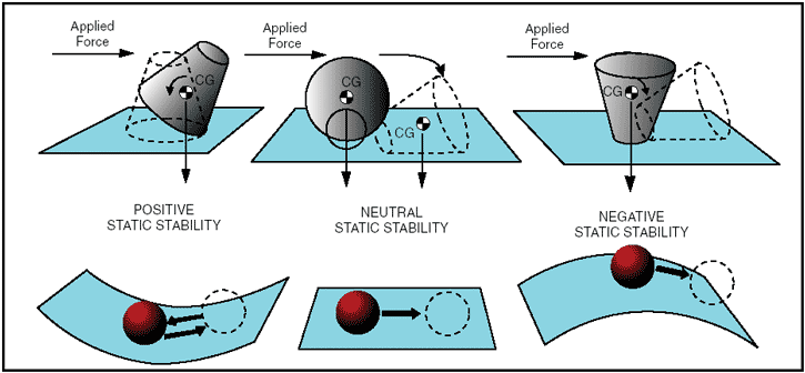
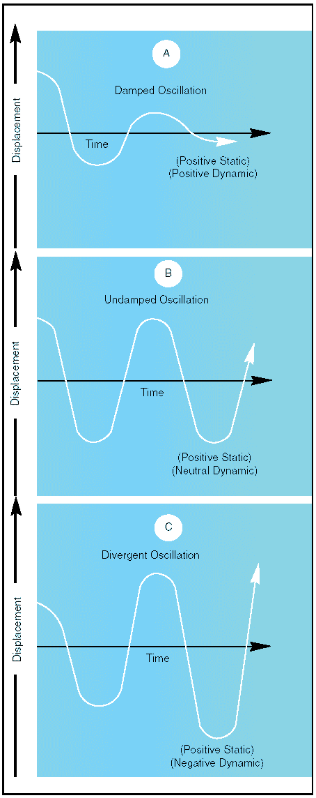
Figure 1: Types of stability. Static stability Stability of an airplane in flight is slightly more complex than just explained, because the airplane is free to move in any direction and must be controllable in pitch, roll, and direction. When designing the airplane, engineers must compromise between stability, maneuverability, and controllability; and the problem is compounded because of the airplane’s three-axis freedom. Too much stability is detrimental to maneuverability, and similarly, not enough stability is detrimental to controllability. In the design of airplanes, compromise between the two is the keyword. Dynamic stability Static stability has been defined as the initial tendency that the airplane displays after being disturbed from its trimmed condition. Occasionally, the initial tendency is different or opposite from the overall tendency, so distinction must be made between the two. Dynamic stability is the overall tendency that the airplane displays after its equilibrium is disturbed. The curves of figure 2 represent the variation of controlled functions versus time. It is seen that the unit of time is very significant. If the time unit for one cycle or oscillation is above 10 seconds’ duration, it is called a “long-period” oscillation (phugoid) and is easily controlled. In a longitudinal phugoid oscillation, the angle of attack remains constant when the airspeed increases and decreases. To a certain degree, a convergent phugoid is desirable but is not required. The phugoid can be determined only on a statically stable airplane, and this has a great effect on the trimming qualities of the airplane. If the time unit for one cycle or oscillation is less than one or two seconds, it is called a “short-period” oscillation and is normally very difficult, if not impossible, for the pilot to control. This is the type of oscillation that the pilot can easily “get in phase with” and reinforce.
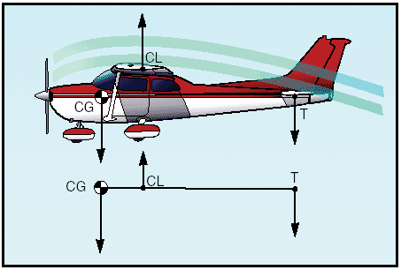
Figure 2: Damped versus undamped stability. A neutral or divergent, short-period oscillation is dangerous because structural failure usually results if the oscillation is not damped immediately. Short-period oscillations affect airplane and control surfaces alike and reveal themselves as “porpoising” in the airplane, or as in “buzz” or “flutter” in the control surfaces. Basically, the short-period oscillation is a change in angle of attack with no change in airspeed. A short-period oscillation of a control surface is usually of such high frequency that the airplane does not have time to react. Logically, the Code of Federal Regulations require that short-period oscillations be heavily damped (i.e., die out immediately). Flight tests during the airworthiness certification of airplanes are conducted for this condition by inducing the oscillation in the controls for pitch, roll, or yaw at the most critical speed (i.e., at VNE, the never-exceed speed). The test pilot strikes the control wheel or rudder pedal a sharp blow and observes the results. Longitudinal stability (pitching) In designing an airplane, a great deal of effort is spent in developing the desired degree of stability around all three axes. But longitudinal stability about the lateral axis is considered to be the most affected by certain variables in various flight conditions. Longitudinal stability is the quality that makes an airplane stable about its lateral axis. It involves the pitching motion as the airplane’s nose moves up and down in flight. Alongitudinally unstable airplane has a tendency to dive or climb progressively into a very steep dive or climb, or even a stall. Thus, an airplane with longitudinal instability becomes difficult and sometimes dangerous to fly. Static longitudinal stability or instability in an airplane, is dependent upon three factors: 1. Location of the wing with respect to the center of gravity; 2. Location of the horizontal tail surfaces with respect to the center of gravity; and 3. The area or size of the tail surfaces. In analyzing stability, it should be recalled that a body that is free to rotate will always turn about its center of gravity. To obtain static longitudinal stability, the relation of the wing and tail moments must be such that, if the moments are initially balanced and the airplane is suddenly nosed up, the wing moments and tail moments will change so that the sum of their forces will provide an unbalanced but restoring moment which, in turn, will bring the nose down again. Similarly, if the airplane is nosed down, the resulting change in moments will bring the nose back up. The center of lift, sometimes called the center of pressure, in most unsymmetrical airfoils has a tendency to change its fore and aft position with a change in the angle of attack. The center of pressure tends to move forward with an increase in angle of attack and to move aft with a decrease in angle of attack. This means that when the angle of attack of an airfoil is increased, the center of pressure (lift) by moving forward, tends to lift the leading edge of the wing still more. This tendency gives the wing an inherent quality of instability. Figure 3 shows an airplane in straight-and-level flight. The line CG-CL-T represents the airplane’s longitudinal axis from the center of gravity (CG) to a point T on the horizontal stabilizer. The center of lift (or center of pressure) is represented by the point CL.
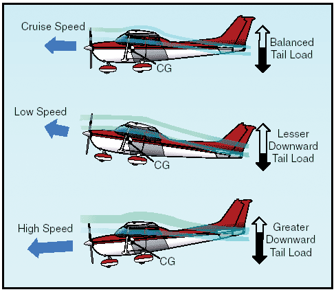
Figure 3: Longitudinal stability. Most airplanes are designed so that the wing’s center of lift (CL) is to the rear of the center of gravity. This makes the airplane “nose heavy” and requires that there be a slight downward force on the horizontal stabilizer in order to balance the airplane and keep the nose from continually pitching downward. Compensation for this nose heaviness is provided by setting the horizontal stabilizer at a slight negative angle of attack. The downward force thus produced, holds the tail down, counterbalancing the “heavy” nose. It is as if the line CG-CL-T was a lever with an upward force at CL and two downward forces balancing each other, one a strong force at the CG point and the other, a much lesser force, at point T (downward air pressure on the stabilizer). Applying simple physics principles, it can be seen that if an iron bar were suspended at point CL with a heavy weight hanging on it at the CG, it would take some downward pressure at point T to keep the “lever” in balance. Even though the horizontal stabilizer may be level when the airplane is in level flight, there is a downwash of air from the wings. This downwash strikes the top of the stabilizer and produces a downward pressure, which at a certain speed will be just enough to balance the “lever.” The faster the airplane is flying, the greater this downwash and the greater the downward force on the horizontal stabilizer (except “T” tails).
Figure 4: Effect of speed on downwash. In airplanes with fixed position horizontal stabilizers, the airplane manufacturer sets the stabilizer at an angle that will provide the best stability (or balance) during flight at the design cruising speed and power setting.
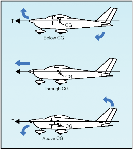
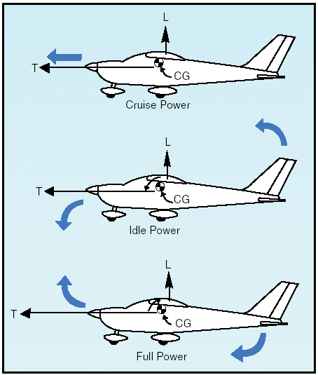
Figure 5: Reduced power allows pitch down. If the airplane’s speed decreases, the speed of the airflow over the wing is decreased. As a result of this decreased flow of air over the wing, the downwash is reduced, causing a lesser downward force on the horizontal stabilizer. In turn, the characteristic nose heaviness is accentuated, causing the airplane’s nose to pitch down more. This places the airplane in a nose-low attitude, lessening the wing’s angle of attack and drag and allowing the airspeed to increase. As the airplane continues in the nose-low attitude and its speed increases, the downward force on the horizontal stabilizer is once again increased. Consequently, the tail is again pushed downward and the nose rises into a climbing attitude. As this climb continues, the airspeed again decreases, causing the downward force on the tail to decrease until the nose lowers once more. However, because the airplane is dynamically stable, the nose does not lower as far this time as it did before. The airplane will acquire enough speed in this more gradual dive to start it into another climb, but the climb is not so steep as the preceding one. After several of these diminishing oscillations, in which the nose alternately rises and lowers, the airplane will finally settle down to a speed at which the downward force on the tail exactly counteracts the tendency of the airplane to dive. When this condition is attained, the airplane will once again be in balanced flight and will continue in stabilized flight as long as this attitude and airspeed are not changed. A similar effect will be noted upon closing the throttle. The downwash of the wings is reduced and the force at T in figure 3 is not enough to hold the horizontal stabilizer down. It is as if the force at T on the lever were allowing the force of gravity to pull the nose down. This, of course, is a desirable characteristic because the airplane is inherently trying to regain airspeed and reestablish the proper balance. Power or thrust can also have a destabilizing effect in that an increase of power may tend to make the nose rise. The airplane designer can offset this by establishing a “high thrustline” wherein the line of thrust passes above the center of gravity.
Figure 6: Thrust line affects longitudinal stability.
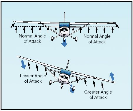
Figure 7: Power changes affect longitudinal stability. In this case, as power or thrust is increased a moment is produced to counteract the down load on the tail. On the other hand, a very “low thrust line” would tend to add to the nose-up effect of the horizontal tail surface. It can be concluded, then, that with the center of gravity forward of the center of lift, and with an aerodynamic tail-down force, the result is that the airplane always tries to return to a safe flying attitude. A simple demonstration of longitudinal stability may be made as follows: Trim the airplane for “hands off” control in level flight. Then momentarily give the controls a slight push to nose the airplane down. If, within a brief period, the nose rises to the original position and then stops, the airplane is statically stable. Ordinarily, the nose will pass the original position (that of level flight) and a series of slow pitching oscillations will follow. If the oscillations gradually cease, the airplane has positive stability; if they continue unevenly, the airplane has neutral stability; if they increase, the airplane is unstable. Lateral stability (rolling) Stability about the airplane’s longitudinal axis, which extends from nose to tail, is called lateral stability. This helps to stabilize the lateral or rolling effect when one wing gets lower than the wing on the opposite side of the airplane. There are four main design factors that make an airplane stable laterally: dihedral, keel effect, sweepback, and weight distribution. The most common procedure for producing lateral stability is to build the wings with a dihedral angle varying from one to three degrees. In other words, the wings on either side of the airplane join the fuselage to form a slight V or angle called “dihedral,” and this is measured by the angle made by each wing above a line parallel to the lateral axis. The basis of rolling stability is, of course, the lateral balance of forces produced by the airplane’s wings. Any imbalance in lift results in a tendency for the airplane to roll about its longitudinal axis. Stated another way, dihedral involves a balance of lift created by the wings’ angle of attack on each side of the airplane’s longitudinal axis. If a momentary gust of wind forces one wing of the airplane to rise and the other to lower, the airplane will bank. When the airplane is banked without turning, it tends to sideslip or slide downward toward the lowered wing.
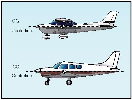
Figure 8: Dihedral for lateral stability. Since the wings have dihedral, the air strikes the low wing at much greater angle of attack than the high wing. This increases the lift on the low wing and decreases lift on the high wing, and tends to restore the airplane to its original lateral attitude (wings level)—that is, the angle of attack and lift on the two wings are again equal. The effect of dihedral, then, is to produce a rolling moment tending to return the airplane to a laterally balanced flight condition when a sideslip occurs. The restoring force may move the low wing up too far, so that the opposite wing now goes down. If so, the process will be repeated, decreasing with each lateral oscillation until a balance for wings-level flight is finally reached. Conversely, excessive dihedral has an adverse effect on lateral maneuvering qualities. The airplane may be so stable laterally that it resists any intentional rolling motion. For this reason, airplanes that require fast roll or banking characteristics usually have less dihedral than those designed for less maneuverability. The contribution of sweepback to dihedral effect is important because of the nature of the contribution. In a sideslip, the wing into the wind is operating with an effective decrease in sweepback, while the wing out of the wind is operating with an effective increase in sweepback. The swept wing is responsive only to the wind component that is perpendicular to the wing’s leading edge. Consequently, if the wing is operating at a positive lift coefficient, the wing into the wind has an increase in lift, and the wing out of the wind has a decrease in lift. In this manner, the swept back wing would contribute a positive dihedral effect and the swept forward wing would contribute a negative dihedral effect. During flight, the side area of the airplane’s fuselage and vertical fin react to the airflow in much the same manner as the keel of a ship. That is, it exerts a steadying influence on the airplane laterally about the longitudinal axis. Such laterally stable airplanes are constructed so that the greater portion of the keel area is above and behind the center of gravity.
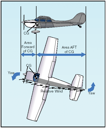
Figure 9: Keel area for lateral stability. Thus, when the airplane slips to one side, the combination of the airplane’s weight and the pressure of the airflow against the upper portion of the keel area (both acting about the CG) tends to roll the airplane back to wings-level flight. Vertical stability (yawing) Stability about the airplane’s vertical axis (the sideways moment) is called yawing or directional stability. Yawing or directional stability is the more easily achieved stability in airplane design. The area of the vertical fin and the sides of the fuselage aft of the center of gravity are the prime contributors which make the airplane act like the well known weathervane or arrow, pointing its nose into the relative wind. In examining a weathervane, it can be seen that if exactly the same amount of surface were exposed to the wind in front of the pivot point as behind it, the forces fore and aft would be in balance and little or no directional movement would result. Consequently, it is necessary to have a greater surface aft of the pivot point that forward of it. Similarly in an airplane, the designer must ensure positive directional stability by making the side surface greater aft than ahead of the center of gravity.
Figure 10: Fuselage and fin for vertical stability. To provide more positive stability aside from that provided by the fuselage, a vertical fin is added. The fin acts similar to the feather on an arrow in maintaining straight flight. Like the weathervane and the arrow, the farther aft this fin is placed and the larger its size, the greater the airplane’s directional stability. If an airplane is flying in a straight line, and a sideward gust of air gives the airplane a slight rotation about its vertical axis (i.e., the right), the motion is retarded and stopped by the fin because while the airplane is rotating to the right, the air is striking the left side of the fin at an angle. This causes pressure on the left side of the fin, which resists the turning motion and slows down the airplane’s yaw. In doing so, it acts somewhat like the weathervane by turning the airplane into the relative wind. The initial change in direction of the airplane’s flightpath is generally slightly behind its change of heading. Therefore, after a slight yawing of the airplane to the right, there is a brief moment when the airplane is still moving along its original path, but its longitudinal axis is pointed slightly to the right. The airplane is then momentarily skidding sideways, and during that moment (since it is assumed that although the yawing motion has stopped, the excess pressure on the left side of the fin still persists) there is necessarily a tendency for the airplane to be turned partially back to the left. That is, there is a momentary restoring tendency caused by the fin. This restoring tendency is relatively slow in developing and ceases when the airplane stops skidding. When it ceases, the airplane will be flying in a direction slightly different from the original direction. In other words, it will not of its own accord return to the original heading; the pilot must reestablish the initial heading. A minor improvement of directional stability may be obtained through sweepback. Sweepback is incorporated in the design of the wing primarily to delay the onset of compressibility during high-speed flight. In lighter and slower airplanes, sweepback aids in locating the center of pressure in the correct relationship with the center of gravity. A longitudinally stable airplane is built with the center of pressure aft of the center of gravity. Because of structural reasons, airplane designers sometimes cannot attach the wings to the fuselage at the exact desired point. If they had to mount the wings too far forward, and at right angles to the fuselage, the center of pressure would not be far enough to the rear to result in the desired amount of longitudinal stability. By building sweepback into the wings, however, the designers can move the center of pressure toward the rear. The amount of sweepback and the position of the wings then place the center of pressure in the correct location. The contribution of the wing to static directional stability is usually small. The swept wing provides a stable contribution depending on the amount of sweepback, but the contribution is relatively small when compared with other components. Free directional oscillations (Dutch roll) Dutch Roll is a coupled lateral/directional oscillation that is usually dynamically stable but is objectionable in an airplane because of the oscillatory nature. The damping of the oscillatory mode may be weak or strong depending on the properties of the particular airplane. Unfortunately all air is not smooth. There are bumps and depressions created by gusty updrafts and downdrafts, and by gusts from ahead, behind, or the side of the airplane. The response of the airplane to a disturbance from equilibrium is a combined rolling/yawing oscillation in which the rolling motion is phased to precede the yawing motion. The yawing motion is not too significant, but the roll is much more noticeable. When the airplane rolls back toward level flight in response to dihedral effect, it rolls back too far and sideslips the other way. Thus, the airplane overshoots each time because of the strong dihedral effect. When the dihedral effect is large in comparison with static directional stability, the Dutch Roll motion has weak damping and is objectionable. When the static directional stability is strong in comparison with the dihedral effect, the Dutch Roll motion has such heavy damping that it is not objectionable. However, these qualities tend toward spiral instability. The choice is then the least of two evils—Dutch Roll is objectionable and spiral instability is tolerable if the rate of divergence is low. Since the more important handling qualities are a result of high static directional stability and minimum necessary dihedral effect, most airplanes demonstrate a mild spiral tendency. This tendency would be indicated to the pilot by the fact that the airplane cannot be flown “hands off” indefinitely. In most modern airplanes, except high-speed swept wing designs, these free directional oscillations usually die out automatically in a very few cycles unless the air continues to be gusty or turbulent. Those airplanes with continuing Dutch Roll tendencies usually are equipped with gyro stabilized yaw dampers. An airplane that has Dutch Roll tendencies is disconcerting, to say the least. Therefore, the manufacturer tries to reach a medium between too much and too little directional stability. Because it is more desirable for the airplane to have “spiral instability” than Dutch Roll tendencies, most airplanes are designed with that characteristic. Spiral instability Spiral instability exists when the static directional stability of the airplane is very strong as compared to the effect of its dihedral in maintaining lateral equilibrium. When the lateral equilibrium of the airplane is disturbed by a gust of air and a sideslip is introduced, the strong directional stability tends to yaw the nose into the resultant relative wind while the comparatively weak dihedral lags in restoring the lateral balance. Due to this yaw, the wing on the outside of the turning moment travels forward faster than the inside wing and as a consequence, its lift becomes greater. This produces an overbanking tendency which, if not corrected by the pilot, will result in the bank angle becoming steeper and steeper. At the same time, the strong directional stability that yaws the airplane into the relative wind is actually forcing the nose to a lower pitch attitude. Then, the start of a slow downward spiral which has begun, if not counteracted by the pilot, will gradually increase into a steep spiral dive. Usually the rate of divergence in the spiral motion is so gradual that the pilot can control the tendency without any difficulty. All airplanes are affected to some degree by this characteristic although they may be inherently stable in all other normal parameters. This tendency would be indicated to the pilot by the fact that the airplane cannot be flown “hands off” indefinitely. Much study and effort has gone into development of control devices (wing leveler) to eliminate or at least correct this instability. Advanced stages of this spiral condition demand that the pilot be very careful in application of recovery controls, or excessive loads on the structure may be imposed. Of the in-flight structural failures that have occurred in general aviation airplanes, improper recovery from this condition has probably been the underlying cause of more fatalities than any other single factor. The reason is that the airspeed in the spiral condition builds up rapidly, and the application of back elevator force to reduce this speed and to pull the nose up only “tightens the turn,” increasing the load factor. The results of the prolonged uncontrolled spiral are always the same; either in-flight structural failure, crashing into the ground, or both. The most common causes on record for getting into this situation are: loss of horizon reference, inability of the pilot to control the airplane by reference to instruments, or a combination of both. This concludes the Aeronautics page. You can now go on to the Load Factors page, or try the FAA Principles of Flight Test. |


