


Flight PlanningTitle 14 of the Code of Federal Regulations (14 CFR) part 91 states, in part, that before beginning a flight, the pilot in command of an aircraft shall become familiar with all available information concerning that flight. For flights not in the vicinity of an airport, this must include information on available current weather reports and forecasts, fuel requirements, alternatives available if the planned flight cannot be completed, and any known traffic delays of which the pilot in command has been advised by air traffic control (ATC). Assembling necessary material The pilot should collect the necessary material well before the flight. An appropriate current sectional chart and charts for areas adjoining the flight route should be among this material if the route of flight is near the border of a chart. Additional equipment should include a flight computer or electronic calculator, plotter, and any other item appropriate to the particular flight—for example, if a night flight is to be undertaken, carry a flashlight; if a flight is over desert country, carry a supply of water and other necessities. Weather check It may be wise to check the weather before continuing with other aspects of flight planning to see, first of all, if the flight is feasible and, if it is, which route is best. Refer to the page on aviation weather reporting for a discussion on obtaining a weather briefing. Use of the Airport/Facility Directory Study available information about each airport at which a landing is intended. This should include a study of the Notices to Airmen (NOTAMs) and the Airport/Facility Directory.
Figure 1: Airport Facility Directory. This includes location, elevation, runway and lighting facilities, available services, availability of aeronautical advisory station frequency (UNICOM), types of fuel available (use to decide on refueling stops), AFSS/FSS located on the airport, control tower and ground control frequencies, traffic information, remarks, and other pertinent information. The NOTAMs, issued every 28 days, should be checked for additional information on hazardous conditions or changes that have been made since issuance of the Airport/Facility Directory. The sectional chart bulletin subsection should be checked for major changes that have occurred since the last publication date of each sectional chart being used. Remember, the chart may be up to 6 months old. The effective date of the chart appears at the top of the front of the chart. The Airport/Facility Directory will generally have the latest information pertaining to such matters and should be used in preference to the information on the back of the chart, if there are differences. Airplane flight manual or pilot’s operating handbook The Airplane Flight Manual or Pilot’s Operating Handbook (AFM/POH) should be checked to determine the proper loading of the airplane (weight and balance data). The weight of the usable fuel and drainable oil aboard must be known. Also, check the weight of the passengers, the weight of all baggage to be carried, and the empty weight of the airplane to be sure that the total weight does not exceed the maximum allowable. The distribution of the load must be known to tell if the resulting center of gravity is within limits. Be sure to use the latest weight and balance information in the FAA-approved Airplane Flight Manual or other permanent airplane records, as appropriate, to obtain empty weight and empty weight center-of-gravity information. The use of weight and balance data is explained on the Weight and Balance page. Determine the takeoff and landing distances from the appropriate charts, based on the calculated load, elevation of the airport, and temperature; then compare these distances with the amount of runway available. Remember, the heavier the load and the higher the elevation, temperature, or humidity, the longer the takeoff roll and landing roll and the lower the rate of climb. Check the fuel consumption charts to determine the rate of fuel consumption at the estimated flight altitude and power settings. Calculate the rate of fuel consumption, and then compare it with the estimated time for the flight so that refueling points along the route can be included in the plan. Basic calculations Before a cross-country flight, a pilot should make common calculations for time, speed, and distance, and the amount of fuel required. Converting minutes to equivalent hours It frequently is necessary to convert minutes into equivalent hours when solving speed, time, and distance problems. To convert minutes to hours, divide by 60 (60 minutes = 1 hour). Thus, 30 minutes 30/60 = 0.5 hour. To convert hours to minutes, multiply by 60. Thus, 0.75 hour equals 0.75 x 60 = 45 minutes. Time T = D/GS To find the time (T) in flight, divide the distance (D) by the groundspeed (GS). The time to fly 210 nautical miles at a groundspeed of 140 knots is 210 divided by 140, or 1.5 hours. (The 0.5 hour multiplied by 60 minutes equals 30 minutes.) Answer: 1:30. Distance D = GS X T To find the distance flown in a given time, multiply groundspeed by time. The distance flown in 1 hour 45 minutes at a groundspeed of 120 knots is 120 x 1.75, or 210 nautical miles. Groundspeed GS = D/T To find the groundspeed, divide the distance flown by the time required. If an airplane flies 270 nautical miles in 3 hours, the groundspeed is 270 divided by 3 = 90 knots. Converting knots to miles per hour Another conversion is that of changing knots to miles per hour. The aviation industry is using knots more frequently than miles per hour, but it might be well to discuss the conversion for those who do use miles per hour when working with speed problems. The National Weather Service reports both surface winds and winds aloft in knots. However, airspeed indicators in some airplanes are calibrated in miles per hour (although many are now calibrated in both miles per hour and knots). Pilots, therefore, should learn to convert windspeeds in knots to miles per hour. A knot is 1 nautical mile per hour. Because there are 6,076.1 feet in a nautical mile and 5,280 feet in a statute mile, the conversion factor is 1.15. To convert knots to miles per hour, multiply knots by 1.15. For example: a windspeed of 20 knots is equivalent to 23 miles per hour. Most flight computers or electronic calculators have a means of making this conversion. Another quick method of conversion is to use the scales of nautical miles and statute miles at the bottom of aeronautical charts. Fuel consumption Airplane fuel consumption is computed in gallons per hour. Consequently, to determine the fuel required for a given flight, the time required for the flight must be known. Time in flight multiplied by rate of consumption gives the quantity of fuel required. For example, a flight of 400 NM at a groundspeed of 100 knots requires 4 hours. If the plane consumes 5 gallons an hour, the total consumption will be 4 x 5, or 20 gallons. The rate of fuel consumption depends on many factors: condition of the engine, propeller pitch, propeller r.p.m., richness of the mixture, and particularly the percentage of horsepower used for flight at cruising speed. The pilot should know the approximate consumption rate from cruise performance charts, or from experience. In addition to the amount of fuel required for the flight, there should be sufficient fuel for reserve. Flight computers Up to this point, only mathematical formulas have been used to determine such items as time, distance, speed, and fuel consumption. In reality, most pilots will use a mechanical or electronic flight computer. These devices can compute numerous problems associated with flight planning and navigation. The mechanical or electronic computer will have an instruction book and most likely sample problems so the pilot can become familiar with its functions and operation. Plotter Another aid in flight planning is a plotter, which is a protractor and ruler. The pilot can use this when determining true course and measuring distance. Most plotters have a ruler which measures in both nautical and statute miles and has a scale for a sectional chart on one side and a world aeronautical chart on the other.
Figure 2: A picture of the computational and wind side of a common mechanical computer, an electronic computer, and plotter. Charting the course Once the weather has been checked and some preliminary planning done, it is time to chart the course and determine the data needed to accomplish the flight. The following sections will provide a logical sequence to follow in charting the course, filling out a flight log, and filing a flight plan. In the following example, a trip is planned based on the following data and the sectional chart excerpt in figure 3.
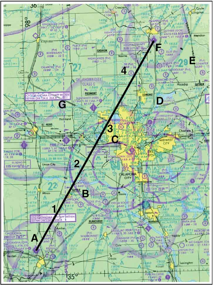
Figure 3: Sectional chart excerpt.
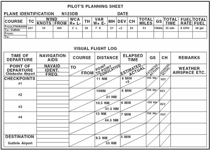
Steps in charting the course The following is a suggested sequence for arriving at the pertinent information for the trip. As information is determined, it may be noted as illustrated in the example of a flight log in figure 4. Where calculations are required, the pilot may use a mathematical formula or a manual or electronic flight computer. If unfamiliar with how to use a manual or electronic computer competently, it would be advantageous to read the operation manual and work several practice problems at this point.
Figure 4: Pilot’s planning sheet and visual flight log. First draw a line from Chickasha Airport (point A) directly to Guthrie Airport (point F). The course line should begin at the center of the airport of departure and end at the center of the destination airport. If the route is direct, the course line will consist of a single straight line. If the route is not direct, it will consist of two or more straight line segments—for example, a VOR station which is off the direct route, but which will make navigating easier, may be chosen (radio navigation is discussed on Practical Navigation Principles page ). Appropriate checkpoints should be selected along the route and noted in some way. These should be easy-to locate points such as large towns, large lakes and rivers, or combinations of recognizable points such as towns with an airport, towns with a network of highways, and railroads entering and departing. Normally, choose only towns indicated by splashes of yellow on the chart. Do not choose towns represented by a small circle —these may turn out to be only a half-dozen houses. (In isolated areas, however, towns represented by a small circle can be prominent checkpoints.) For this trip, four checkpoints have been selected. Checkpoint 1 consists of a tower located east of the course and can be further identified by the highway and railroad track, which almost parallels the course at this point. Checkpoint 2 is the obstruction just to the west of the course and can be further identified by Will Rogers Airport which is directly to the east. Checkpoint 3 is Wiley Post Airport, which the airplane should fly directly over. Checkpoint 4 is a private non-surfaced airport to the west of the course and can be further identified by the railroad track and highway to the east of the course. The course and areas on either side of the planned route should be checked to determine if there is any type of airspace with which the pilot should be concerned or which has special operational requirements. For this trip, it should be noted that the course will pass through a segment of the Class C airspace surrounding Will Rogers Airport where the floor of the airspace is 2,500 feet mean sea level (MSL) and the ceiling is 5,300 feet MSL (point B). Also, there is Class D airspace from the surface to 3,800 feet MSL surrounding Wiley Post Airport (point C) during the time the control tower is in operation. Study the terrain and obstructions along the route. This is necessary to determine the highest and lowest elevations as well as the highest obstruction to be encountered so that an appropriate altitude which will conform to part 91 regulations can be selected. If the flight is to be flown at an altitude more than 3,000 feet above the terrain, conformance to the cruising altitude appropriate to the direction of flight is required. Check the route for particularly rugged terrain so it can be avoided. Areas where a takeoff or landing will be made should be carefully checked for tall obstructions. TV transmitting towers may extend to altitudes over 1,500 feet above the surrounding terrain. It is essential that pilots be aware of their presence and location. For this trip, it should be noted that the tallest obstruction is part of a series of antennas with a height of 2,749 feet MSL (point D). The highest elevation should be located in the northeast quadrant and is 2,900 feet MSL (point E). Since the wind is no factor and it is desirable and within the airplane’s capability to fly above the Class C and D airspace to be encountered, an altitude of 5,500 feet MSL will be chosen. This altitude also gives adequate clearance of all obstructions as well as conforms to the part 91 requirement to fly at an altitude of odd thousand plus 500 feet when on a magnetic course between 0 and 179°. Next, the pilot should measure the total distance of the course as well as the distance between checkpoints. The total distance is 53 NM and the distance between checkpoints is as noted on the flight log in figure 4. After determining the distance, the true course should be measured. If using a plotter, follow the directions on the plotter. The true course is 031°. Once the true heading is established, the pilot can determine the compass heading. This is done by following the formula given below: TC ± WCA = TH ± VAR = MH ± DEV = CH The wind correction angle can be determined by using a manual or electronic flight computer. Using a wind of 360° at 10 knots, it is determined the WCA is 3° left. This is subtracted from the TC making the TH 28°. Next, the pilot should locate the isogonic line closest to the route of the flight to determine variation. Point G in figure 3 shows the variation to be 6° 30_E (rounded to 7°E), which means it should be subtracted from the TH, giving an MH of 21°. Next, add 2° to the MH for the deviation correction. This gives the pilot the compass heading which is 23°. Next, the groundspeed should be determined. This can be done using a manual or electronic calculator. It is determined the GS is 106 knots. Based on this information, the total trip time, as well as time between checkpoints, and the fuel burned can be determined. These calculations can be done mathematically or by using a manual or electronic calculator. For this trip, the GS is 106 knots and the total time is 35 minutes (30 minutes plus 5 minutes for climb) with a fuel burn of 4.7 gallons. Refer to the flight log in figure 4 for the time between checkpoints. As the trip progresses, the pilot can note headings and time and make adjustments in heading, groundspeed, and time. Filing a VFR flight plan Filing a flight plan is not required by regulations; however, it is a good operating practice, since the information contained in the flight plan can be used in search and rescue in the event of an emergency. Flight plans can be filed in the air by radio, but it is best to file a flight plan either in person at the FSS or by phone just before departing. After takeoff, contact the FSS by radio and give them the takeoff time so the flight plan can be activated. When a VFR flight plan is filed, it will be held by the FSS until 1 hour after the proposed departure time and then canceled unless: the actual departure time is received; or a revised proposed departure time is received; or at the time of filing, the FSS is informed that the proposed departure time will be met, but actual time cannot be given because of inadequate communication. The FSS specialist who accepts the flight plan will not inform the pilot of this procedure, however.
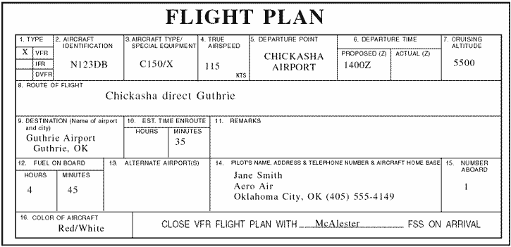
Figure 5: Flight plan form. Figure 5 shows the flight plan form a pilot files with the Flight Service Station. When filing a flight plan by telephone or radio, give the information in the order of the numbered spaces. This enables the FSS specialist to copy the information more efficiently. Most of the spaces are either self-explanatory or nonapplicable to the VFR flight plan (such as item 13). However, some spaces may need explanation.
Remember, there is every advantage in filing a flight plan; but do not forget to close the flight plan on arrival. Do this by telephone with the nearest FSS, if possible, to avoid radio congestion. Lost procedures Getting lost in an airplane is a potentially dangerous situation especially when low on fuel. If a pilot becomes lost, there are some good common sense procedures to follow. If a town or city cannot be seen, the first thing to do is climb, being mindful of traffic and weather conditions. An increase in altitude increases radio and navigation reception range, and also increases radar coverage. If flying near a town or city, it might be possible to read the name of the town on a water tower. If the airplane has a navigational radio, such as a VOR or ADF receiver, it can be possible to determine position by plotting an azimuth from two or more navigational facilities. If GPS is installed, or a pilot has a portable aviation GPS on board, it can be used to determine the position and the location of the nearest airport. Communicate with any available facility using frequencies shown on the sectional chart. If contact is made with a controller, radar vectors may be offered. Other facilities may offer direction finding (DF) assistance. To use this procedure, the controller will request the pilot to hold down the transmit button for a few seconds and then release it. The controller may ask the pilot to change directions a few times and repeat the transmit procedure. This gives the controller enough information to plot the airplane position and then give vectors to a suitable landing site. If the situation becomes threatening, transmit the situation on the emergency frequency 121.5 MHz and set the transponder to 7700. Most facilities, and even airliners, monitor the emergency frequency. Flight diversion There will probably come a time when a pilot will not be able to make it to the planned destination. This can be the result of unpredicted weather conditions, a system malfunction, or poor preflight planning. In any case, the pilot will need to be able to safely and efficiently divert to an alternate destination. Before any cross-country flight, check the charts for airports or suitable landing areas along or near the route of flight. Also, check for navigational aids that can be used during a diversion. Computing course, time, speed, and distance information in flight requires the same computations used during preflight planning. However, because of the limited cockpit space, and because attention must be divided between flying the airplane, making calculations, and scanning for other airplanes, take advantage of all possible shortcuts and rule-of-thumb computations. When in flight, it is rarely practical to actually plot a course on a sectional chart and mark checkpoints and distances. Furthermore, because an alternate airport is usually not very far from your original course, actual plotting is seldom necessary. A course to an alternate can be measured accurately with a protractor or plotter, but can also be measured with reasonable accuracy using a straight edge and the compass rose depicted around VOR stations. This approximation can be made on the basis of a radial from a nearby VOR or an airway that closely parallels the course to your alternate. However, remember that the magnetic heading associated with a VOR radial or printed airway is outbound from the station. To find the course TO the station, it may be necessary to determine the reciprocal of that heading. It is typically easier to navigate to an alternate airport that has a VOR or NDB facility on the field. After selecting the most appropriate alternate, approximate the magnetic course to the alternate using a compass rose or airway on the sectional chart. If time permits, try to start the diversion over a prominent ground feature. However, in an emergency, divert promptly toward your alternate. To complete all plotting, measuring, and computations involved before diverting to the alternate may only aggravate an actual emergency. Once established on course, note the time, and then use the winds aloft nearest to your diversion point to calculate a heading and groundspeed. Once a groundspeed has been calculated, determine a new arrival time and fuel consumption. Give priority to flying the airplane while dividing attention between navigation and planning. When determining an altitude to use while diverting, consider cloud heights, winds, terrain, and radio reception. This concludes the Flight Planning page. You can now go to the Aeronautical Decision Making page or test your knowledge on the FAA Flight Operations test question bank. |