


Flight controls: How an airplane is controlled.Axes of an airplane Whenever an airplane changes its flight attitude or position in flight, it rotates about one or more of three axes, which are imaginary lines that pass through the airplane’s center of gravity. The axes of an airplane can be considered as imaginary axles around which the airplane turns, much like the axle around which a wheel rotates. At the point where all three axes intersect, each is at a 90° angle to the other two. The axis, which extends lengthwise through the fuselage from the nose to the tail, is the longitudinal axis. The axis, which extends crosswise from wingtip to wingtip, is the lateral axis. The axis, which passes vertically through the center of gravity, is the vertical axis. 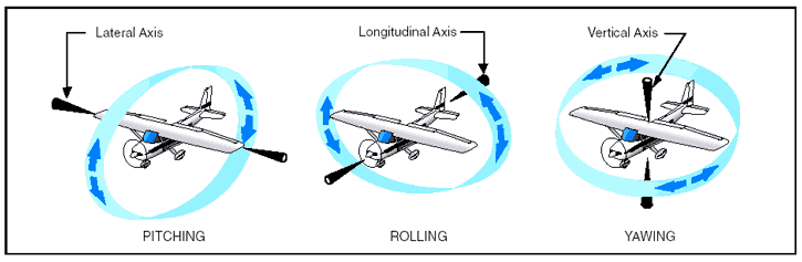
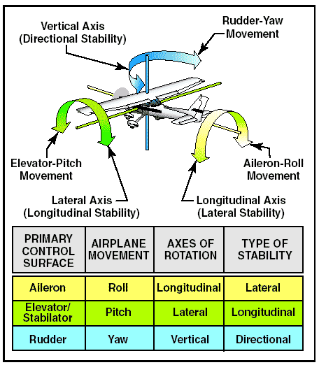
Figure 1: Axes of an airplane. The airplane’s motion about its longitudinal axis resembles the roll of a ship from side to side. In fact, the names used in describing the motion about an airplane’s three axes were originally nautical terms. They have been adapted to aeronautical terminology because of the similarity of motion between an airplane and the seagoing ship. In light of the adoption of nautical terms, the motion about the airplane’s longitudinal axis is called “roll”; motion about its lateral axis is referred to as “pitch.” Finally, an airplane moves about its vertical axis in a motion, which is termed “yaw”—that is, a horizontal (left and right) movement of the airplane’s nose. The three motions of the airplane (roll, pitch, and yaw) are controlled by three control surfaces. Roll is controlled by the ailerons; pitch is controlled by the elevators; yaw is controlled by the rudder. The use of these controls is explained further down on this page. Moments and moment arm A study of physics shows that a body that is free to rotate will always turn about its center of gravity. In aerodynamic terms, the mathematical measure of an airplane’s tendency to rotate about its center of gravity is called a “moment.” A moment is said to be equal to the product of the force applied and the distance at which the force is applied. (A moment arm is the distance from a datum [reference point or line] to the applied force.) For airplane weight and balance computations, “moments” are expressed in terms of the distance of the arm times the airplane’s weight, or simply, inch pounds. Airplane designers locate the fore and aft position of the airplane’s center of gravity as nearly as possible to the 20 percent point of the mean aerodynamic chord (MAC). If the thrust line is designed to pass horizontally through the center of gravity, it will not cause the airplane to pitch when power is changed, and there will be no difference in moment due to thrust for a power-on or power-off condition of flight. Although designers have some control over the location of the drag forces, they are not always able to make the resultant drag forces pass through the center of gravity of the airplane. However, the one item over which they have the greatest control is the size and location of the tail. The objective is to make the moments (due to thrust, drag, and lift) as small as possible; and, by proper location of the tail, to provide the means of balancing the airplane longitudinally for any condition of flight. The pilot has no direct control over the location of forces acting on the airplane in flight, except for controlling the center of lift by changing the angle of attack. Such a change, however, immediately involves changes in other forces. Therefore, the pilot cannot independently change the location of one force without changing the effect of others. For example, a change in airspeed involves a change in lift, as well as a change in drag and a change in the up or down force on the tail. As forces such as turbulence and gusts act to displace the airplane, the pilot reacts by providing opposing control forces to counteract this displacement. Some airplanes are subject to changes in the location of the center of gravity with variations of load. Trimming devices are used to counteract the forces set up by fuel burnoff, and loading or off-loading of passengers or cargo. Elevator trim tabs and adjustable horizontal stabilizers comprise the most common devices provided to the pilot for trimming for load variations. Over the wide ranges of balance during flight in large airplanes, the force which the pilot has to exert on the controls would become excessive and fatiguing if means of trimming were not provided. Aircraft flight control systems are classified as primary and secondary. The primary control systems consist of those that are required to safely control an airplane during flight. These include the ailerons, elevator (or stabilator), and rudder. Secondary control systems improve the performance characteristics of the airplane, or relieve the pilot of excessive control forces. Examples of secondary control systems are wing flaps and trim systems. Primary flight controls Airplane control systems are carefully designed to provide a natural feel, and at the same time, allow adequate responsiveness to control inputs. At low airspeeds, the controls usually feel soft and sluggish, and the airplane responds slowly to control applications. At high speeds, the controls feel firm and the response is more rapid. Movement of any of the three primary flight control surfaces changes the airflow and pressure distribution over and around the airfoil. These changes affect the lift and drag produced by the airfoil/control surface combination, and allow a pilot to control the airplane about its three axes of rotation. Design features limit the amount of deflection of flight control surfaces. For example, control-stop mechanisms may be incorporated into the flight controls, or movement of the control column and/or rudder pedals may be limited. The purpose of these design limits is to prevent the pilot from inadvertently overcontrolling and overstressing the aircraft during normal maneuvers. A properly designed airplane should be stable and easily controlled during maneuvering. Control surface inputs cause movement about the three axes of rotation. The types of stability an airplane exhibits also relate to the three axes of rotation.
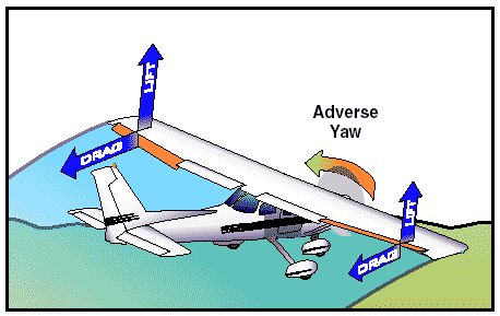
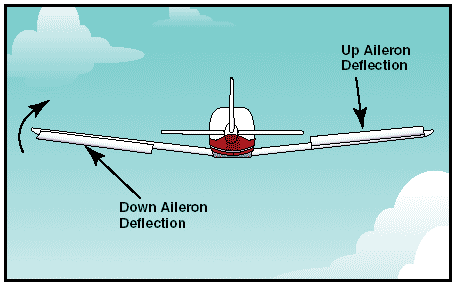
Figure 2: Airplane controls, movement, axes of rotation, and type of stability. Ailerons Ailerons control roll about the longitudinal axis. The ailerons are attached to the outboard trailing edge of each wing and move in the opposite direction from each other. Ailerons are connected by cables, bellcranks, pulleys or push-pull tubes to each other and to the control wheel. Moving the control wheel to the right causes the right aileron to deflect upward and the left aileron to deflect downward. The upward deflection of the right aileron decreases the camber resulting in decreased lift on the right wing. The corresponding downward deflection of the left aileron increases the camber resulting in increased lift on the left wing. Thus, the increased lift on the left wing and the decreased lift on the right wing causes the airplane to roll to the right. Adverse yaw Since the downward deflected aileron produces more lift, it also produces more drag. This added drag attempts to yaw the airplane’s nose in the direction of the raised wing. This is called adverse yaw.
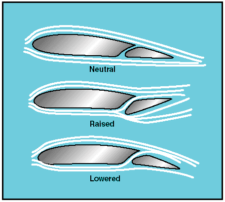
Figure 3: Adverse yaw is caused by higher drag on the outside wing, which is producing more lift. The rudder is used to counteract adverse yaw, and the amount of rudder control required is greatest at low airspeeds, high angles of attack, and with large aileron deflections. However, with lower airspeeds, the vertical stabilizer/rudder combination becomes less effective, and magnifies the control problems associated with adverse yaw. All turns are coordinated by use of ailerons, rudder, and elevator. Applying aileron pressure is necessary to place the airplane in the desired angle of bank, while simultaneously applying rudder pressure to counteract the resultant adverse yaw. During a turn, the angle of attack must be increased by applying elevator pressure because more lift is required than when in straight-and level flight. The steeper the turn, the more back elevator pressure is needed. As the desired angle of bank is established, aileron and rudder pressures should be relaxed. This will stop the bank from increasing because the aileron and rudder control surfaces will be neutral in their streamlined position. Elevator pressure should be held constant to maintain a constant altitude. The rollout from a turn is similar to the roll-in except the flight controls are applied in the opposite direction. Aileron and rudder are applied in the direction of the rollout or toward the high wing. As the angle of bank decreases, the elevator pressure should be relaxed as necessary to maintain altitude. Differential Ailerons With differential ailerons, one aileron is raised a greater distance than the other aileron is lowered for a given movement of the control wheel. This produces an increase in drag on the descending wing. The greater drag results from deflecting the up aileron on the descending wing to a greater angle than the down aileron on the rising wing. While adverse yaw is reduced, it is not eliminated completely.
Figure 4: Differential ailerons. Frise-type ailerons With a Frise-type aileron, when pressure is applied to the control wheel, the aileron that is being raised pivots on an offset hinge. This projects the leading edge of the aileron into the airflow and creates drag. This helps equalize the drag created by the lowered aileron on the opposite wing and reduces adverse yaw.
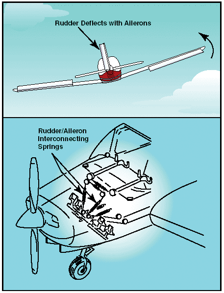
Figure 5: Frise-type ailerons. The Frise-type aileron also forms a slot so that air flows smoothly over the lowered aileron, making it more effective at high angles of attack. Frise-type ailerons also may be designed to function differentially. Like the differential aileron, the Frise-type aileron does not eliminate adverse yaw entirely. Coordinated rudder application is still needed wherever ailerons are applied. Coupled ailerons and rudder Coupled ailerons and rudder means these controls are linked. This is accomplished with rudder-aileron interconnect springs, which help correct for aileron drag by automatically deflecting the rudder at the same time the ailerons are deflected. For example, when the control yoke is moved to produce a left roll, the interconnect cable and spring pulls forward on the left rudder pedal just enough to prevent the nose of the airplane from yawing to the right. The force applied to the rudder by the springs can be overridden if it becomes necessary to slip the airplane.
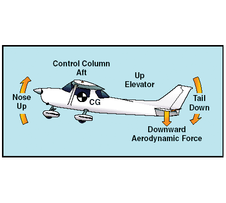
Figure 6: Coupled ailerons and rudder. Elevator The elevator controls pitch about the lateral axis. Like the ailerons on small airplanes, the elevator is connected to the control column in the cockpit by a series of mechanical linkages. Aft movement of the control column deflects the trailing edge of the elevator surface up. This is usually referred to as up elevator.
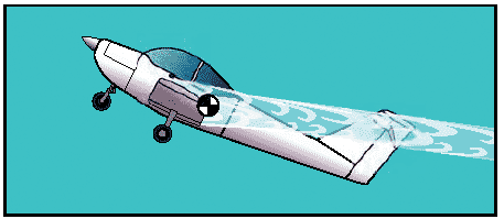
Figure 7: The elevator is the primary control for changing the pitch attitude of an airplane. The up-elevator position decreases the camber of the elevator and creates a downward aerodynamic force, which is greater than the normal tail-down force that exists in straight-and-level flight. The overall effect causes the tail of the airplane to move down and the nose to pitch up. The pitching moment occurs about the center of gravity (CG). The strength of the pitching moment is determined by the distance between the CG and the horizontal tail surface, as well as by the aerodynamic effectiveness of the horizontal tail surface. Moving the control column forward has the opposite effect. In this case, elevator camber increases, creating more lift (less tail-down force) on the horizontal stabilizer/elevator. This moves the tail upward and pitches the nose down. Again, the pitching moment occurs about the CG. As mentioned in the page on stability , power, thrustline, and the position of the horizontal tail surfaces on the empennage are factors in how effective the elevator is in controlling pitch. For example, the horizontal tail surfaces may be attached near the lower part of the vertical stabilizer, at the midpoint, or at the high point, as in the T-tail design. T-tail In a T-tail configuration, the elevator is above most of the effects of downwash from the propeller as well as airflow around the fuselage and/or wings during normal flight conditions. Operation of the elevators in this undisturbed air makes for control movements that are consistent throughout most flight regimes. T-tail designs have become popular on many light airplanes and on large aircraft, especially those with aft-fuselage mounted engines since the T-tail configuration removes the tail from the exhaust blast of the engines. Seaplanes and amphibians often have T-tails in order to keep the horizontal surfaces as far from the water as possible. An additional benefit is reduced vibration and noise inside the aircraft. At slow speeds, the elevator on a T-tail aircraft must be moved through a larger number of degrees of travel to raise the nose a given amount as compared to a conventional-tail aircraft. This is because the conventional-tail aircraft has the downwash from the propeller pushing down on the tail to assist in raising the nose. Since controls on aircraft are rigged in such a manner as to require increasing control forces for increased control travel, the forces required to raise the nose of a T-tail aircraft are greater than for a conventional-tail aircraft. Longitudinal stability of a trimmed aircraft is the same for both types of configuration, but the pilot must be aware that at slow speeds during takeoffs and landings or stalls, the control forces will be greater than for similar size airplanes equipped with conventional tails. T-tail airplanes also require additional design considerations to counter the problem of flutter. Since the weight of the horizontal surfaces is at the top of the vertical stabilizer, the moment arm created causes high loads on the vertical stabilizer which can result in flutter. Engineers must compensate for this by increasing the design stiffness of the vertical stabilizer, usually resulting in a weight penalty over conventional tail designs. When flying at a very high angle of attack with a low airspeed and an aft CG, the T-tail airplane may be susceptible to a deep stall. In a deep stall, the airflow over the horizontal tail is blanketed by the disturbed airflow from the wings and fuselage. In these circumstances, elevator or stabilator control could be diminished, making it difficult to recover from the stall. It should be noted that an aft CG could be a contributing factor in these incidents since similar recovery problems are also found with conventional-tail aircraft with an aft CG.
Figure 8: Airplane with a T-tail design at a high angle of attack and an aft CG. Since flight at a high angle of attack with a low airspeed and an aft CG position can be dangerous, many airplanes have systems to compensate for this situation. The systems range from control stops to elevator down springs. An elevator down spring assists in lowering the nose to prevent a stall caused by the aft CG position. The stall occurs because the properly trimmed airplane is flying with the elevator in a trailing edge down position, forcing the tail up and the nose down. In this unstable condition, if the airplane encounters turbulence and slows down further, the trim tab no longer positions the elevator in the nose-down position. The elevator then streamlines, and the nose of the aircraft pitches upward. This aggravates the situation and can possibly result in a stall. The elevator down spring produces a mechanical load on the elevator, causing it to move toward the nosedown position if not otherwise balanced. The elevator trim tab balances the elevator down spring to position the elevator in a trimmed position. When the trim tab becomes ineffective, the down spring drives the elevator to a nose down position. The nose of the aircraft lowers, speed builds up, and a stall is prevented.
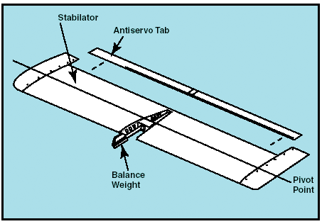
Figure 9: When the aerodynamic efficiency of the horizontal tail surface is inadequate due to an aft center of gravity condition, an elevator down spring may be used to supply a mechanical load to lower the nose. The elevator must also have sufficient authority to hold the nose of the airplane up during the roundout for a landing. In this case, a forward CG may cause a problem. During the landing flare, power normally is reduced, which decreases the airflow over the empennage. This, coupled with the reduced landing speed, makes the elevator less effective. From this discussion, it should be apparent that pilots must understand and follow proper loading procedures, particularly with regard to the CG position. Click here for more information on aircraft loading, as well as weight and balance. Stabilator A stabilator is essentially a one-piece horizontal stabilizer with the same type of control system. Because stabilators pivot around a central hinge point, they are extremely sensitive to control inputs and aerodynamic loads. Antiservo tabs are incorporated on the trailing edge to decrease sensitivity. In addition, a balance weight is usually incorporated ahead of the main spar. The balance weight may project into the empennage or may be incorporated on the forward portion of the stabilator tips.
Figure 10: The stabilator is a one-piece horizontal tail surface that pivots up and down about a central hinge point. When the control column is pulled back, it raises the stabilator’s trailing edge, rotating the airplane’s nose up. Pushing the control column forward lowers the trailing edge of the stabilator and pitches the nose of the airplane down. Without an antiservo tab, the airplane would be prone to overcontrolling from pilot-induced control inputs. Canard The term canard refers to a control surface that functions as a horizontal stabilizer but is located in front of the main wings. The term also is used to describe an airplane equipped with a canard. In effect, it is an airfoil similar to the horizontal surface on a conventional aft-tail design. The difference is that the canard actually creates lift and holds the nose up, as opposed to the aft-tail design which exerts downward force on the tail to prevent the nose from rotating downward. Although the Wright Flyer was configured as a canard with the horizontal surfaces in front of the lifting surface, it was not until recently that the canard configuration began appearing on newer airplanes. Canard designs include two types—one with a horizontal surface of about the same size as a normal aft-tail design, and the other with a surface of the same approximate size and airfoil of the aft-mounted wing known as a tandem wing configuration. Theoretically, the canard is considered more efficient because using the horizontal surface to help lift the weight of the aircraft should result in less drag for a given amount of lift. The canard’s main advantage is in the area of stall characteristics. A properly designed canard or tandem wing will run out of authority to raise the nose of the aircraft at a point before the main wing will stall. This makes the aircraft stall-proof and results only in a descent rate that can be halted by adding power. Ailerons on the main wing remain effective throughout the recovery. Other canard configurations are designed so the canard stalls before the main wing, automatically lowering the nose and recovering the aircraft to a safe flying speed. Again, the ailerons remain effective throughout the stall. The canard design has several limitations. First, it is important that the forward lifting surface of a canard design stalls before the main wing. If the main wing stalls first, the lift remaining from the forward wing or canard would be well ahead of the CG, and the airplane would pitch up uncontrollably. Second, when the forward surface stalls first, or is limited in its ability to increase the angle of attack, the main wing never reaches a point where its maximum lift is created, sacrificing some performance. Third, use of flaps on the main wing causes design problems for the forward wing or canard. As lift on the main wing is increased by extension of flaps, the lift requirement of the canard is also increased. The forward wing or canard must be large enough to accommodate flap use, but not so large that it creates more lift than the main wing. Finally, the relationship of the main wing to the forward surface also makes a difference. When positioned closely in the vertical plane, downwash from the forward wing can have a negative effect on the lift of the main wing. Increasing vertical separation increases efficiency of the design. Efficiency is also increased as the size of the two surfaces grows closer to being equal. Rudder The rudder controls movement of the airplane about its vertical axis. This motion is called yaw. Like the other primary control surfaces, the rudder is a movable surface hinged to a fixed surface, in this case, to the vertical stabilizer, or fin. Moving the left or right rudder pedal controls the rudder. When the rudder is deflected into the airflow, a horizontal force is exerted in the opposite direction.
Figure 11: The effect of left rudder pressure. By pushing the left pedal, the rudder moves left. This alters the airflow around the vertical stabilizer/rudder, and creates a sideward lift that moves the tail to the right and yaws the nose of the airplane to the left. Rudder effectiveness increases with speed, so large deflections at low speeds and small deflections at high speeds may be required to provide the desired reaction. In propeller-driven aircraft, any slipstream flowing over the rudder increases its effectiveness. V-tail The V-tail design utilizes two slanted tail surfaces to perform the same functions as the surfaces of a conventional elevator and rudder configuration. The fixed surfaces act as both horizontal and vertical stabilizers.
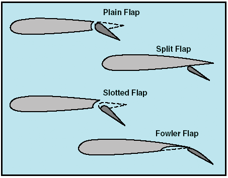
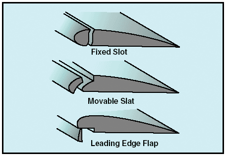
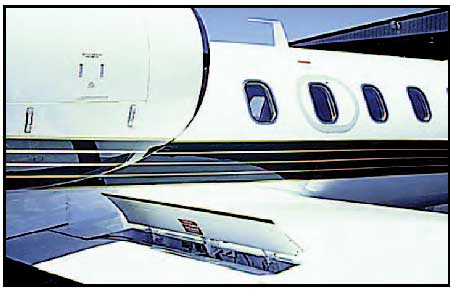
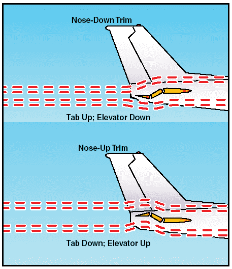
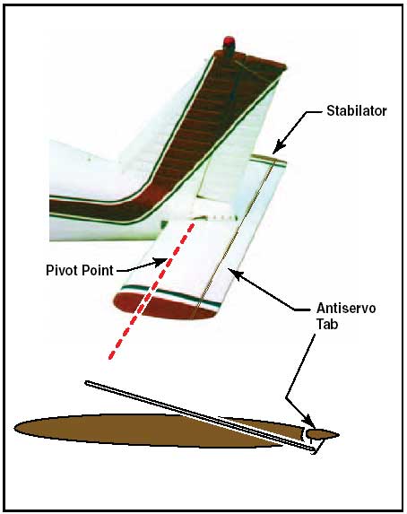
Figure 12: V-tail design. The movable surfaces, which are usually called ruddervators, are connected through a special linkage that allows the control wheel to move both surfaces simultaneously. On the other hand, displacement of the rudder pedals moves the surfaces differentially, thereby providing directional control. When both rudder and elevator controls are moved by the pilot, a control mixing mechanism moves each surface the appropriate amount. The control system for the V-tail is more complex than that required for a conventional tail. In addition, the V-tail design is more susceptible to Dutch roll tendencies than a conventional tail and total reduction in drag is only minimal. Secondary flight controls Secondary flight control systems may consist of the flaps, leading edge devices, spoilers, and trim devices. Flaps Flaps are the most common high-lift devices used on practically all airplanes. These surfaces, which are attached to the trailing edge of the wing, increase both lift and induced drag for any given angle of attack. Figure 13: Four common types of flaps. The plain flap is the simplest of the four types. It increases the airfoil camber, resulting in a significant increase in the coefficient of lift at a given angle of attack. At the same time, it greatly increases drag and moves the center of pressure aft on the airfoil, resulting in a nose-down pitching moment. The split flap is deflected from the lower surface of the airfoil and produces a slightly greater increase in lift than does the plain flap. However, more drag is created because of the turbulent air pattern produced behind the airfoil. When fully extended, both plain and split flaps produce high drag with little additional lift. The most popular flap on airplanes today is the slotted flap. Variations of this design are used for small airplanes as well as for large ones. Slotted flaps increase the lift coefficient significantly more than plain or spilt flaps. On small airplanes, the hinge is located below the lower surface of the flap, and when the flap is lowered, it forms a duct between the flap well in the wing and the leading edge of the flap. When the slotted flap is lowered, high-energy air from the lower surface is ducted to the flap’s upper surface. The high-energy air from the slot accelerates the upper surface boundary layer and delays airflow separation, providing a higher coefficient of lift. Thus, the slotted flap produces much greater increases in CLmax than the plain or split flap. While there are many types of slotted flaps, large airplanes often have double- and even triple-slotted flaps. These allow the maximum increase in drag without the airflow over the flaps separating and destroying the lift they produce. Fowler flaps are a type of slotted flap. This flap design not only changes the camber of the wing, it also increases the wing area. Instead of rotating down on a hinge, it slides backwards on tracks. In the first portion of its extension, it increases the drag very little, but increases the lift a great deal as it increases both the area and camber. As the extension continues, the flap deflects downward, and during the last portion of its travel, it increases the drag with little additional increase in lift. Leading edge devices High-lift devices also can be applied to the leading edge of the airfoil. The most common types are fixed slots, movable slats, and leading edge flaps. Figure 14: Leading edge high lift devices. Fixed slots direct airflow to the upper wing surface and delay airflow separation at higher angles of attack. The slot does not increase the wing camber, but allows a higher maximum coefficient of lift because the stall is delayed until the wing reaches a greater angle of attack. Movable slats consist of leading edge segments, which move on tracks. At low angles of attack, each slat is held flush against the wing’s leading edge by the high pressure that forms at the wing’s leading edge. As the angle of attack increases, the high-pressure area moves aft below the lower surface of the wing, allowing the slats to move forward. Some slats, however, are pilot operated and can be deployed at any angle of attack. Opening a slat allows the air below the wing to flow over the wing’s upper surface, delaying airflow separation. Leading edge flaps, like trailing edge flaps, are used to increase both CLmax and the camber of the wings. This type of leading edge device is frequently used in conjunction with trailing edge flaps and can reduce the nose-down pitching movement produced by the latter. As is true with trailing edge flaps, a small increment of leading edge flaps increases lift to a much greater extent than drag. As greater amounts of flaps are extended, drag increases at a greater rate than lift. Spoilers On some airplanes, high-drag devices called spoilers are deployed from the wings to spoil the smooth airflow, reducing lift and increasing drag. Spoilers are used for roll control on some aircraft, one of the advantages being the elimination of adverse yaw. To turn right, for example, the spoiler on the right wing is raised, destroying some of the lift and creating more drag on the right. The right wing drops, and the airplane banks and yaws to the right. Deploying spoilers on both wings at the same time allows the aircraft to descend without gaining speed. Spoilers are also deployed to help shorten ground roll after landing. By destroying lift, they transfer weight to the wheels, improving braking effectiveness. Figure 15: Spoilers reduce lift and increase drag during descent and landing. Trim systems Although the airplane can be operated throughout a wide range of attitudes, airspeeds, and power settings, it can only be designed to fly hands off within a very limited combination of these variables. Therefore, trim systems are used to relieve the pilot of the need to maintain constant pressure on the flight controls. Trim systems usually consist of cockpit controls and small hinged devices attached to the trailing edge of one or more of the primary flight control surfaces. They are designed to help minimize a pilot’s workload by aerodynamically assisting movement and position of the flight control surface to which they are attached. Common types of trim systems include trim tabs, balance tabs, antiservo tabs, ground adjustable tabs, and an adjustable stabilizer. Trim tabs The most common installation on small airplanes is a single trim tab attached to the trailing edge of the elevator. Most trim tabs are manually operated by a small, vertically mounted control wheel. However, a trim crank may be found in some airplanes. The cockpit control includes a tab position indicator. Placing the trim control in the full nose-down position moves the tab to its full up position. With the tab up and into the airstream, the airflow over the horizontal tail surface tends to force the trailing edge of the elevator down. This causes the tail of the airplane to move up, and results in a nose-down pitch change. Figure 16: The movement of the elevator is opposite to the direction of movement of the elevator trim tab. If you set the trim tab to the full nose-up position, the tab moves to its full-down position. In this case, the air flowing under the horizontal tail surface hits the tab and tends to force the trailing edge of the elevator up, reducing the elevator’s angle of attack. This causes a tail-down movement of the airplane and a nose-up pitch change. In spite of the opposite direction movement of the trim tab and the elevator, control of trim is natural to a pilot. If you have to exert constant back pressure on the control column, the need for nose-up trim is indicated. The normal trim procedure is to continue trimming until the airplane is balanced and the nose-heavy condition is no longer apparent. Pilots normally establish the desired power, pitch attitude, and configuration first, and then trim the airplane to relieve control pressures that may exist for that flight condition. Any time power, pitch attitude, or configuration is changed, expect that retrimming will be necessary to relieve the control pressures for the new flight condition. Balance tabs The control forces may be excessively high in some airplanes, and in order to decrease them, the manufacturer may use balance tabs. They look like trim tabs and are hinged in approximately the same places as trim tabs. The essential difference between the two is that the balancing tab is coupled to the control surface rod so that when the primary control surface is moved in any direction, the tab automatically moves in the opposite direction. In this manner, the airflow striking the tab counter-balances some of the air pressure against the primary control surface, and enables the pilot to more easily move and hold the control surface in position. If the linkage between the tab and the fixed surface is adjustable from the cockpit, the tab acts as a combination trim and balance tab, which can be adjusted to any desired deflection. Any time the control surface is deflected, the tab moves in the opposite direction and eases the load on the pilot. Antiservo tabs In addition to decreasing the sensitivity of the stabilator, an antiservo tab also functions as a trim device to relieve control pressure and maintain the stabilator in the desired position. The fixed end of the linkage is on the opposite side of the surface from the horn on the tab, and when the trailing edge of the stabilator moves up, the linkage forces the trailing edge of the tab up. When the stabilator moves down, the tab also moves down. This is different than trim tabs on elevators, which move opposite of the control surface. Figure 17: An antiservo tab attempts to streamline the control surface and is used to make the stabilator less sensitive by opposing the force exerted by the pilot. This tab works in the same manner as the balance tab except that, instead of moving in the opposite direction, it moves in the same direction as the trailing edge of the stabilator. For example, when the trailing edge of the stabilator moves up, the linkage forces the trailing edge of the tab up. When the stabilator moves down, the tab also moves down. Ground adjustable tabs Many small airplanes have a non-moveable metal trim tab on the rudder. This tab is bent in one direction or the other while on the ground to apply a trim force to the rudder. The correct displacement is determined by trial-and-error process. Usually, small adjustments are necessary until you are satisfied that the airplane is no longer skidding left or right during normal cruising flight. Figure 18: A ground-adjustable tab is used on the rudder of many small airplanes to correct for a tendency to fly with the fuselage slightly misaligned with the relative wind. Adjustable stabilizer Rather than using a movable tab on the trailing edge of the elevator, some airplanes have an adjustable stabilizer. With this arrangement, linkages pivot the horizontal stabilizer about its rear spar. This is accomplished by use of a jackscrew mounted on the leading edge of the stabilator. Figure 19: Some airplanes, including most jet transports, use an adjustable stabilizer to provide the required pitch trim forces. On small airplanes, the jackscrew is cable-operated with a trim wheel or crank, and on larger airplanes, it is motor driven. The trimming effect and cockpit indications for an adjustable stabilizer are similar to those of a trim tab. Since the primary and secondary flight control systems vary extensively between aircraft, you need to be familiar with the systems in your aircraft. A good source of information is the Airplane Flight Manual (AFM) or the Pilot’s Operating Handbook (POH). |