


Airplane aerodynamics: fundamentals and flight principles.Fundamentals of aerodynamics Air Air, like any other fluid, is able to flow and change its shape when subjected to even minute pressures because of the lack of strong molecular cohesion. For example, gas will completely fill any container into which it is placed, expanding or contracting to adjust its shape to the limits of the container. Because air has mass and weight, it is a body, and as a body, it reacts to the scientific laws of bodies in the same manner as other gaseous bodies. This body of air resting upon the surface of the earth has weight and at sea level develops an average pressure of 14.7 pounds on each square inch of surface, or 29.92 inches of mercury—but as its thickness is limited, the higher the altitude, the less air there is above. For this reason, the weight of the atmosphere at 18,000 feet is only one-half what it is at sea level. Pressure Though there are various kinds of pressure, this discussion is mainly concerned with atmospheric pressure. It is one of the basic factors in weather changes, helps to lift the airplane, and actuates some of the important flight instruments in the airplane. These instruments are the altimeter, the airspeed indicator, the rate-of-climb indicator, and the manifold pressure gauge. Though air is very light, it has mass and is affected by the attraction of gravity. Therefore, like any other substance, it has weight, and because of its weight, it has force. Since it is a fluid substance, this force is exerted equally in all directions, and its effect on bodies within the air is called pressure. Under standard conditions at sea level, the average pressure exerted on the human body by the weight of the atmosphere around it is approximately 14.7 lb./sqin. Density The density of air has significant effects on the airplane’s capability. As air becomes less dense, it reduces (1) power because the engine takes in less air, (2) thrust because the propeller is less efficient in thin air, and (3) lift because the thin air exerts less force on the airfoils. Effects of pressure on density Since air is a gas, it can be compressed or expanded. When air is compressed, a greater amount of air can occupy a given volume. Conversely, when pressure on a given volume of air is decreased, the air expands and occupies a greater space. That is, the original column of air at a lower pressure contains a smaller mass of air. In other words, the density is decreased. In fact, density is directly proportional to pressure. If the pressure is doubled, the density is doubled, and if the pressure is lowered, so is the density. This statement is true, only at a constant temperature. Effects of temperature on density The effect of increasing the temperature of a substance is to decrease its density. Conversely, decreasing the temperature has the effect of increasing the density. Thus, the density of air varies inversely as the absolute temperature varies. This statement is true, only at a constant pressure. In the atmosphere, both temperature and pressure decrease with altitude, and have conflicting effects upon density. However, the fairly rapid drop in pressure as altitude is increased usually has the dominating effect. Hence, density can be expected to decrease with altitude. Effects of humidity on density The preceding paragraphs have assumed that the air was perfectly dry. In reality, it is never completely dry. The small amount of water vapor suspended in the atmosphere may be almost negligible under certain conditions, but in other conditions humidity may become an important factor in the performance of an airplane. Water vapor is lighter than air; consequently, moist air is lighter than dry air. It is lightest or least dense when, in a given set of conditions, it contains the maximum amount of water vapor. The higher the temperature, the greater amount of water vapor the air can hold. When comparing two separate air masses, the first warm and moist (both qualities tending to lighten the air) and the second cold and dry (both qualities making it heavier), the first necessarily must be less dense than the second. Pressure, temperature, and humidity have a great influence on airplane performance, because of their effect upon density. Bernoulli's principle of pressure Three centuries ago, Mr. Daniel Bernoulli, a Swiss mathematician, explained how the pressure of a moving fluid (liquid or gas) varies with its speed of motion. Specifically, he stated that an increase in the speed of movement or flow would cause a decrease in the fluid’s pressure. This is exactly what happens to air passing over the curved top of the airplane wing. A practical application of Bernoulli’s theorem is the venturi tube. The venturi tube has an air inlet which narrows to a throat (constricted point) and an outlet section which increases in diameter toward the rear. The diameter of the outlet is the same as that of the inlet. At the throat, the airflow speeds up and the pressure decreases; at the outlet, the airflow slows and the pressure increases. 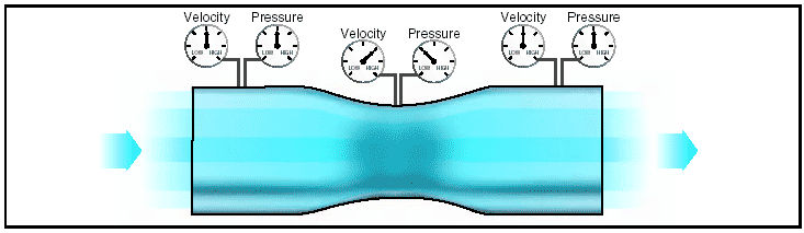
Figure 1: Air pressure decreases in a venturi. Air flow Air has viscosity, and will encounter resistance to flow over a surface. The viscous nature of airflow reduces the local velocities on a surface and is responsible for skin friction drag. As the air passes over the wing’s surface, the air particles nearest the surface come to rest. The next layer of particles is slowed down but not stopped. Some small but measurable distance from the surface, the air particles are moving at free stream velocity. The layer of air over the wing’s surface, which is slowed down or stopped by viscosity, is termed the “boundary layer.” Typical boundary layer thicknesses on an airplane range from small fractions of an inch near the leading edge of a wing to the order of 12 inches at the aft end of a large airplane such as a Boeing 747. There are two different types of boundary layer flow: laminar and turbulent. The laminar boundary layer is a very smooth flow, while the turbulent boundary layer contains swirls or “eddies.” The laminar flow creates less skin friction drag than the turbulent flow, but is less stable. Boundary layer flow over a wing surface begins as a smooth laminar flow. As the flow continues back from the leading edge, the laminar boundary layer increases in thickness. At some distance back from the leading edge, the smooth laminar flow breaks down and transitions to a turbulent flow. From a drag standpoint, it is advisable to have the transition from laminar to turbulent flow as far aft on the wing as possible, or have a large amount of the wing surface within the laminar portion of the boundary layer. The low energy laminar flow, however, tends to break down more suddenly than the turbulent layer. 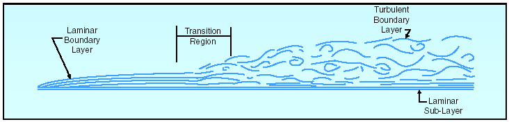
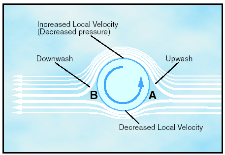
Figure 2: Boundary layer. Another phenomenon associated with viscous flow is separation. Separation occurs when the airflow breaks away from an airfoil. The natural progression is from laminar boundary layer to turbulent boundary layer and then to airflow separation. Airflow separation produces high drag and ultimately destroys lift. The boundary layer separation point moves forward on the wing as the angle of attack is increased. Magnus effect The explanation of lift can best be explained by looking at a cylinder rotating in an airstream. The local velocity near the cylinder is composed of the airstream velocity and the cylinder’s rotational velocity, which decreases with distance from the cylinder. On a cylinder, which is rotating in such a way that the top surface area is rotating in the same direction as the airflow, the local velocity at the surface is high on top and low on the bottom. As shown in figure 3, at point “A,” a stagnation point exists where the airstream line that impinges on the surface splits; some air goes over and some under. Another stagnation point exists at “B,” where the two airstreams rejoin and resume at identical velocities. We now have upwash ahead of the rotating cylinder and downwash at the rear. The difference in surface velocity accounts for a difference in pressure, with the pressure being lower on the top than the bottom. This low pressure area produces an upward force known as the “Magnus Effect.” This mechanically induced circulation illustrates the relationship between circulation and lift. An airfoil with a positive angle of attack develops air circulation as its sharp trailing edge forces the rear stagnation point to be aft of the trailing edge, while the front stagnation point is below the leading edge.
Figure 3: The Magnus effect is a lifting effect produced, when a rotating cylinder produces a pressure differential. If air is recognized as a body and it is accepted that it must follow the above laws, one can begin to see how and why an airplane wing develops lift as it moves through the air. Airplane aerodynamics Airfoil design It has already been discussed in general terms the question of how an airplane wing can sustain flight when the airplane is heavier than air. Perhaps the explanation can best be reduced to its most elementary concept by stating that lift (flight) is simply the result of fluid flow (air) about an airfoil—or in everyday language, the result of moving an airfoil (wing), by whatever means, through the air. Since it is the airfoil which harnesses the force developed by its movement through the air, a discussion and explanation of this structure will be presented. An airfoil is a structure designed to obtain reaction upon its surface from the air through which it moves or that moves past such a structure. Air acts in various ways when submitted to different pressures and velocities; but this discussion will be confined to the parts of an airplane that a pilot is most concerned with in flight—namely, the airfoils designed to produce lift. By looking at a typical airfoil profile, such as the cross section of a wing, one can see several obvious characteristics of design.
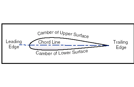
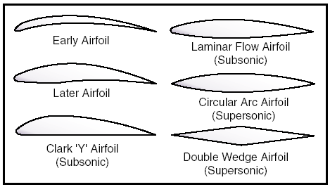
Figure 4: Typical airfoil section. Notice that there is a difference in the curvatures of the upper and lower surfaces of the airfoil (the curvature is called camber). The camber of the upper surface is more pronounced than that of the lower surface, which is somewhat flat in most instances. In figure 4, note that the two extremities of the airfoil profile also differ in appearance. The end which faces forward in flight is called the leading edge, and is rounded; while the other end, the trailing edge, is quite narrow and tapered. A reference line often used in discussing the airfoil is the chord line, a straight line drawn through the profile connecting the extremities of the leading and trailing edges. The distance from this chord line to the upper and lower surfaces of the wing denotes the magnitude of the upper and lower camber at any point. Another reference line, drawn from the leading edge to the trailing edge, is the “mean camber line.” This mean line is equidistant at all points from the upper and lower contours. The construction of the wing, so as to provide actions greater than its weight, is done by shaping the wing so that advantage can be taken of the air’s response to certain physical laws, and thus develop two actions from the air mass; a positive pressure lifting action from the air mass below the wing, and a negative pressure lifting action from lowered pressure above the wing. The fact that most lift is the result of the airflow’s downwash from above the wing, must be thoroughly understood in order to continue further in the study of flight. It is neither accurate nor does it serve a useful purpose, however, to assign specific values to the percentage of lift generated by the upper surface of an airfoil versus that generated by the lower surface. These are not constant values and will vary, not only with flight conditions, but with different wing designs. It should be understood that different airfoils have different flight characteristics. Many thousands of airfoils have been tested in wind tunnels and in actual flight, but no one airfoil has been found that satisfies every flight requirement. The weight, speed, and purpose of each airplane dictate the shape of its airfoil. It was learned many years ago that the most efficient airfoil for producing the greatest lift was one that had a concave, or “scooped out” lower surface. Later it was also learned that as a fixed design, this type of airfoil sacrificed too much speed while producing lift and, therefore, was not suitable for high-speed flight. It is interesting to note, however, that through advanced progress in engineering, today’s high-speed jets can again take advantage of the concave airfoil’s high lift characteristics. Leading edge (Kreuger) flaps and trailing edge (Fowler) flaps, when extended from the basic wing structure, literally change the airfoil shape into the classic concave form, thereby generating much greater lift during slow flight conditions. On the other hand, an airfoil that is perfectly streamlined and offers little wind resistance sometimes does not have enough lifting power to take the airplane off the ground. Thus, modern airplanes have airfoils which strike a medium between extremes in design, the shape varying according to the needs of the airplane for which it is designed. Figure 5 shows some of the more common airfoil sections.
Figure 5: Airfoil designs. Momentum effects of airflow In a wind tunnel or in flight, an airfoil is simply a streamlined object inserted into a moving stream of air. If the airfoil profile were in the shape of a teardrop, the speed and the pressure changes of the air passing over the top and bottom would be the same on both sides. But if the teardrop shaped airfoil were cut in half lengthwise, a form resembling the basic airfoil (wing) section would result. If the airfoil were then inclined so the airflow strikes it at an angle (angle of attack), the air molecules moving over the upper surface would be forced to move faster than would the molecules moving along the bottom of the airfoil, since the upper molecules must travel a greater distance due to the curvature of the upper surface. This increased velocity reduces the pressure above the airfoil. Bernoulli’s principle of pressure by itself does not explain the distribution of pressure over the upper surface of the airfoil. A discussion of the influence of momentum of the air as it flows in various curved paths near the airfoil will be presented. 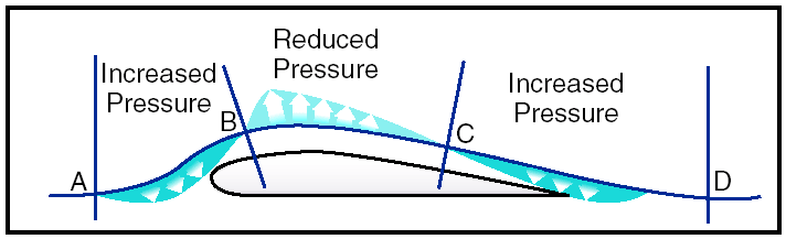
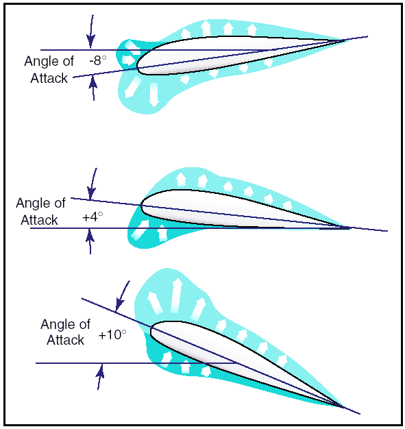
Figure 6: Momentum influences airflow over an airfoil. Momentum is the resistance a moving body offers to having its direction or amount of motion changed. When a body is forced to move in a circular path, it offers resistance in the direction away from the center of the curved path. This is “centrifugal force.” While the particles of air move in the curved path AB, centrifugal force tends to throw them in the direction of the arrows between A and B and hence, causes the air to exert more than normal pressure on the leading edge of the airfoil. But after the air particles pass B (the point of reversal of the curvature of the path) the centrifugal force tends to throw them in the direction of the arrows between B and C (causing reduced pressure on the airfoil). This effect is held until the particles reach C, the second point of reversal of curvature of the airflow. Again the centrifugal force is reversed and the particles may even tend to give slightly more than normal pressure on the trailing edge of the airfoil, as indicated by the short arrows between C and D. Therefore, the air pressure on the upper surface of the airfoil is distributed so that the pressure is much greater on the leading edge than the surrounding atmospheric pressure, causing strong resistance to forward motion; but the air pressure is less than surrounding atmospheric pressure over a large portion of the top surface (B to C). Fluid flow or airflow then, is the basis for flight in airplanes, and is a product of the velocity of the airplane. The velocity of the airplane is very important to the pilot since it affects the lift and drag forces of the airplane. The pilot uses the velocity (airspeed) to fly at a minimum glide angle, at maximum endurance, and for a number of other flight maneuvers. Airspeed is the velocity of the airplane relative to the air mass through which it is flying. Pressure distribution From experiments conducted on wind tunnel models and on full size airplanes, it has been determined that as air flows along the surface of a wing at different angles of attack, there are regions along the surface where the pressure is negative, or less than atmospheric, and regions where the pressure is positive, or greater than atmospheric. This negative pressure on the upper surface creates a relatively larger force on the wing than is caused by the positive pressure resulting from the air striking the lower wing surface. Figure 7 shows the pressure distribution along an airfoil at three different angles of attack. In general, at high angles of attack the center of pressure moves forward, while at low angles of attack the center of pressure moves aft. In the design of wing structures, this center of pressure travel is very important, since it affects the position of the airloads imposed on the wing structure in low angle-of-attack conditions and high angle-of-attack conditions. The airplane’s aerodynamic balance and controllability are governed by changes in the center of pressure.
Figure 7: Pressure distribution on an airfoil. The center of pressure is determined through calculation and wind tunnel tests by varying the airfoil’s angle of attack through normal operating extremes. As the angle of attack is changed, so are the various pressure distribution characteristics.
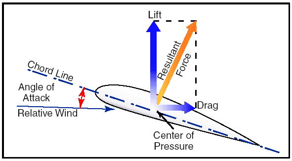
Figure 8: Force vectors on an airfoil. Positive (+) and negative (–) pressure forces are totaled for each angle of attack and the resultant force is obtained. The total resultant pressure is represented by the resultant force vector shown in figure 8. The point of application of this force vector is termed the “center of pressure” (CP). For any given angle of attack, the center of pressure is the point where the resultant force crosses the chord line. This point is expressed as a percentage of the chord of the airfoil. A center of pressure at 30 percent of a 60-inch chord would be 18 inches aft of the wing’s leading edge. It would appear then that if the designer would place the wing so that its center of pressure was at the airplane’s center of gravity, the airplane would always balance. The difficulty arises, however, that the location of the center of pressure changes with change in the airfoil’s angle of attack.
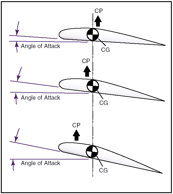
Figure 9: CP changes with an angle of attack. In the airplane’s normal range of flight attitudes, if the angle of attack is increased, the center of pressure moves forward; and if decreased, it moves rearward. Since the center of gravity is fixed at one point, it is evident that as the angle of attack increases, the center of lift (CL) moves ahead of the center of gravity, creating a force which tends to raise the nose of the airplane or tends to increase the angle of attack still more. On the other hand, if the angle of attack is decreased, the center of lift (CL) moves aft and tends to decrease the angle a greater amount. It is seen then, that the ordinary airfoil is inherently unstable, and that an auxiliary device, such as the horizontal tail surface, must be added to make the airplane balance longitudinally. The balance of an airplane in flight depends, therefore, on the relative position of the center of gravity (CG) and the center of pressure (CP) of the airfoil. Experience has shown that an airplane with the center of gravity in the vicinity of 20 percent of the wing chord can be made to balance and fly satisfactorily. Airplane loading and weight distribution also affect center of gravity and cause additional forces, which in turn affect airplane balance. This concludes the Airplane Aerodynamics Page. You can now test how much you remember from this page at the
Airplane Aerodynamics question bank
or read on at the
Flight Controls Page.
|